Methods and apparatus for treating water and wastewater employing a cloth filter

Active Publication Date: 2016-03-03
ALFA LAVAL CORP AB
View PDF39 Cites 12 Cited by
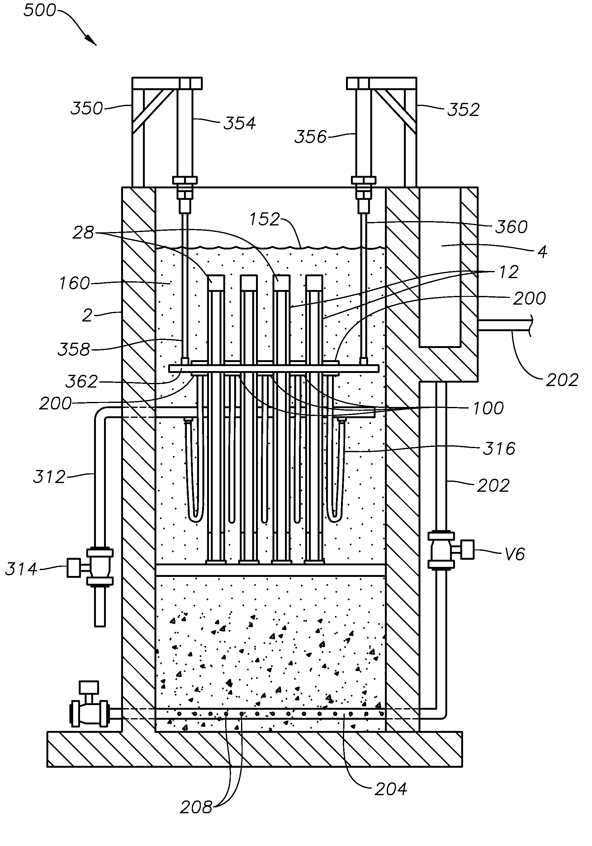
  • Summary
  • Abstract
  • Description
  • Claims
  • Application Information

AI Technical Summary

Benefits of technology

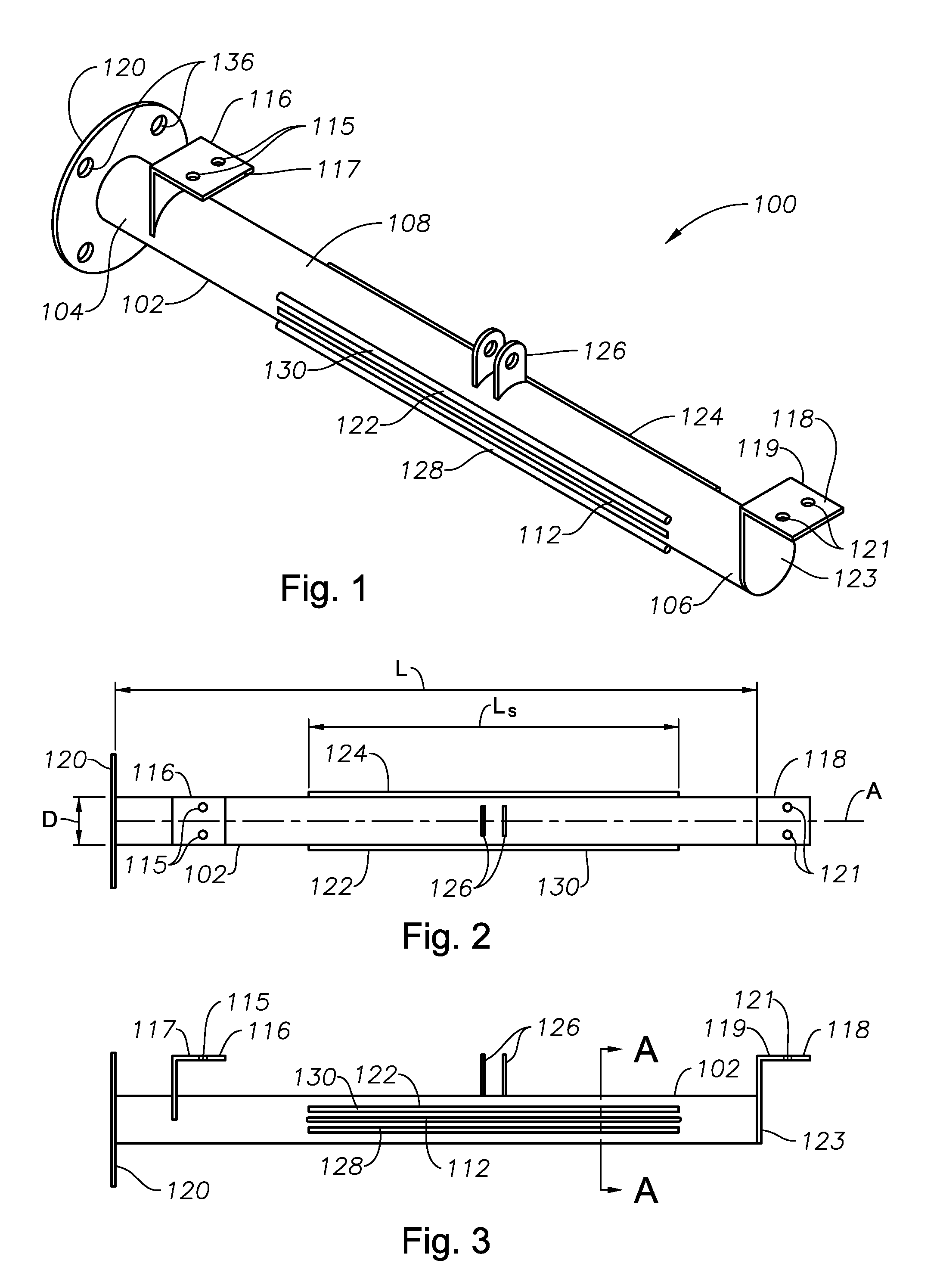
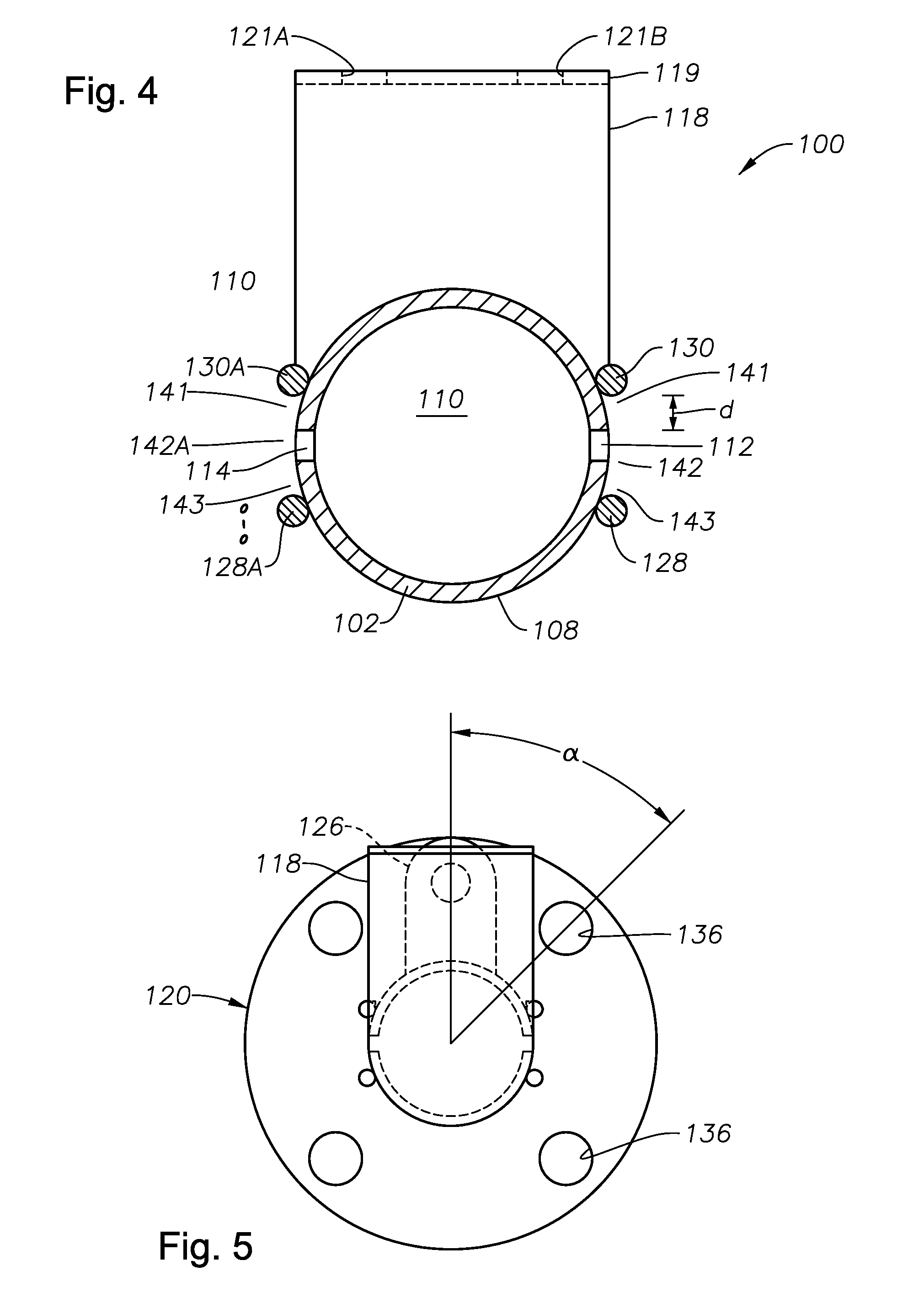
[0014]wherein the open-ended sub-chambers have sufficient volume to allow gradual straightening and relaxing of fibers of a filter material being cleaned by the apparatus, and allow relatively clean fluid to pass through the filter material in a reverse direction upon application of a suction pressure in t

Problems solved by technology

In particular, in the older shoes the leading edge of the flat underside may compress, squeeze, and dislodge captured solids out of the reach of the suction of the backwash system; and even worse may force solids through the cloth to the filtered water side, thereby contaminating the filtered water.
The flat underside may not

Method used


Image

  • Methods and apparatus for treating water and wastewater employing a cloth filter
  • Methods and apparatus for treating water and wastewater employing a cloth filter
  • Methods and apparatus for treating water and wastewater employing a cloth filter

Examples


Embodiment Construction

[0046]In the following description, numerous details are set forth to provide an understanding of the disclosed backwash headers, cloth filters using same, and methods of their use. However, it will be understood by those skilled in the art that the backwash headers, cloth filters and methods may be practiced without these details and that numerous variations or modifications from the described embodiments may be possible. All U.S. published patent applications and U.S. patents referenced herein, as well as any non-published U.S. patent applications and published non-patent literature are hereby explicitly incorporated herein by reference. In the event definitions of terms in the referenced patents and applications conflict with how those terms are defined in the present application, the definitions for those terms that are provided in the present application shall be deemed controlling.

[0047]Certain backwash header embodiments of the present disclosure may employ as the body a circ...


PUM

PropertyMeasurementUnit
Massaaaaaaaaaa
Lengthaaaaaaaaaa
Pressureaaaaaaaaaa

Abstract

A backwash header for a cloth filter includes a body having a length, a diameter, first and second ends, a longitudinal axis, and an exterior surface, the body defining at least one internal cavity. The body includes at least one suction slot sized to allow fluids and solids to enter the internal cavity from outside of the exterior surface. A structure is attached to a portion of the exterior surface of the body around and extending away from the suction slot to form an open-ended chamber defined by the structure and a portion of the exterior surface near the suction slot. The structure allows fluids and solids to enter the open-ended chamber and then the suction slot and cavity from a material being cleaned. Cloth filters and methods of treating water and wastewater using the backwash headers and cloth filters.

Description

BACKGROUND INFORMATION[0001]1. Technical Field[0002]The present disclosure relates in general to the field of water and wastewater treatment.[0003]2. Background Art[0004]A cloth filter typically comprises a tank or vessel, which may be concrete, metal, fiberglass-reinforced plastic (FRP) or other material. A source of screened, secondary effluent flows into the unit from an influent trough, and filtered effluent leaves the unit through an effluent trough. Influent may traverse an influent weir, a scum or hydraulic optimization baffle, then approaches one or more filter cassettes. In currently known systems, each filter cassette may have at least one dedicated backwash vacuum shoe assembly positioned on one side of filter cloth fluidly attached to the central rotatable backwash conduit. In some other known embodiments the filter cassettes rotate during backwashing, while the backwash shoes remain stationary. One such backwash shoe is described in assignee's U.S. Pat. No. ______ (S 40...

Claims


Application Information

Patent Timeline
IPC IPC(8): B01D29/68B01D29/39B01D29/64C02F1/00
CPCB01D29/684C02F1/004B01D29/688B01D2201/082B01D29/39C02F1/52C02F2303/24B01D29/64B01D29/05B01D35/10C02F1/56C02F2209/42C02F2303/16
Inventor DANNEMANN, CHARLES, G.
Owner ALFA LAVAL CORP AB
Why Eureka
Try Eureka