Hydrogen production system and method for producing hydrogen

a production system and hydrogen technology, applied in the field of hydrogen production field, can solve the problems of large reaction containment, difficult supply of steam used for electrolysis, complicated configuration inside containment, etc., and achieve the effect of high-efficiency hydrogen production

Active Publication Date: 2016-03-03
KK TOSHIBA
View PDF0 Cites 18 Cited by
  • Summary
  • Abstract
  • Description
  • Claims
  • Application Information

AI Technical Summary

Benefits of technology

[0013]To solve the problems described above, it is the object of the present invention to provide a technique for producing hydrogen that achieves highly-efficient hydrogen production even when hydrogen is produced by using the plurality of cell stacks.
[0014]A hydrogen production system according to an embodiment of the present invention includes a plurality of cell stacks that are installed in a reaction containment, the cell stacks generating hydrogen by high temperature steam electrolysis by supplying steam to the plurality of cell stacks, a first flow path guiding the steam to each of the cell stacks, a second flow path causing a carrier gas containing air as a main component to flow into the reaction containment, and a flow regulation device provided at an inlet of the steam in each of the cell stacks, the flow regulation device regulating a flow rate of the steam supplied into each of the cell stacks to be uniform.

Problems solved by technology

However, as the number of the arranged cell stacks is increased, the reaction containment becomes large, and a configuration inside the containment becomes complicated.
Therefore, it becomes difficult to supply steam used for the electrolytic reaction to uniformly flow into each of the cell stacks.
If the steam to be supplied into each of the cell stacks does not keep uniform, the electrolytic reactions are not evenly performed in the cell stacks, and the hydrogen production efficiency is lowered.
If flow rates of the steam flowing into the cell stacks become uneven, and the steam becomes deficient (steam starvation state) in some of the cell stacks, the electrolytic reaction cannot be stably continued, and the electrolytic cell may be damaged.

Method used


Image

  • Hydrogen production system and method for producing hydrogen
  • Hydrogen production system and method for producing hydrogen
  • Hydrogen production system and method for producing hydrogen

Examples


first embodiment

[0026]Hereinafter, embodiments of the present invention are described based on the accompanying drawings.

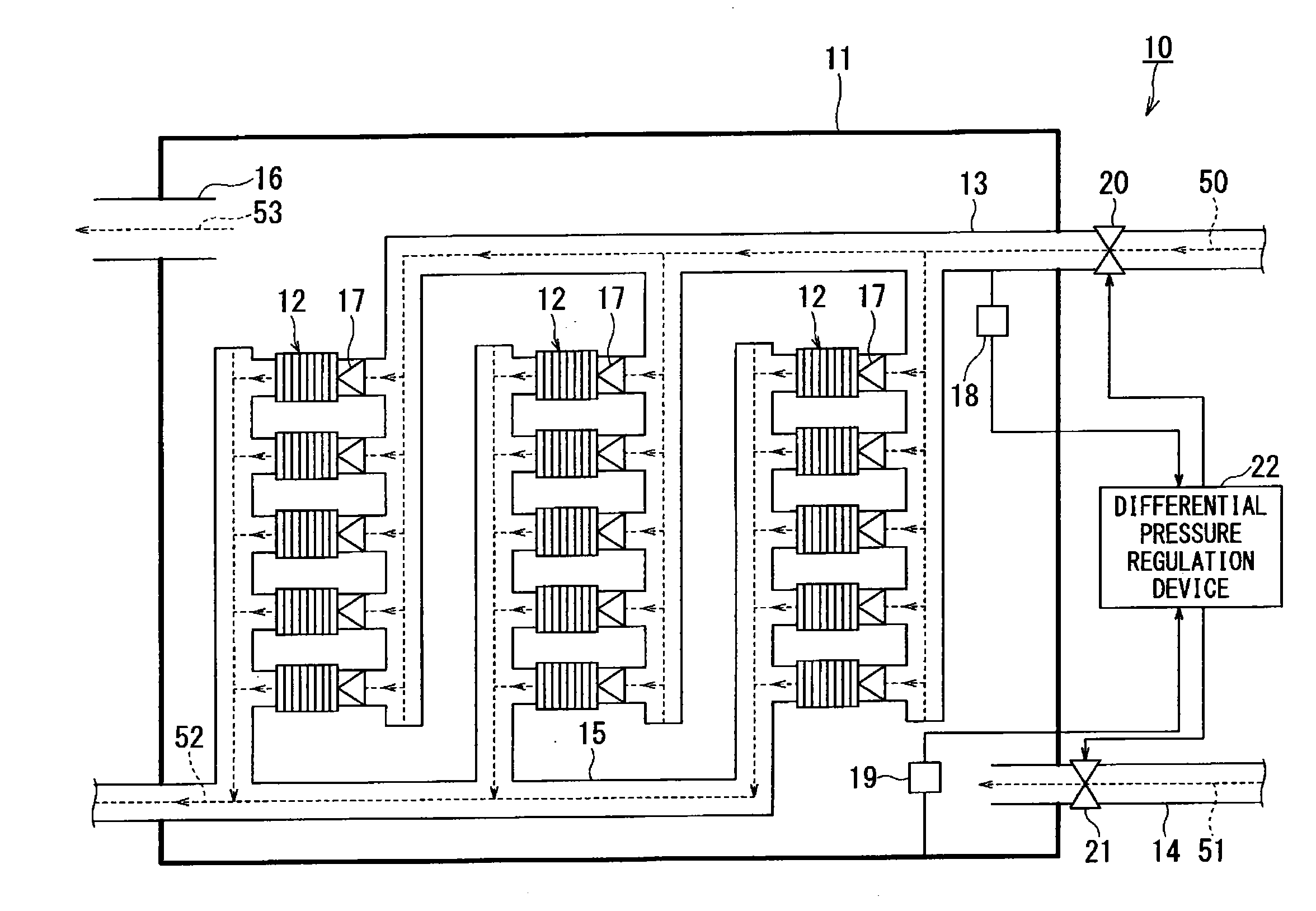
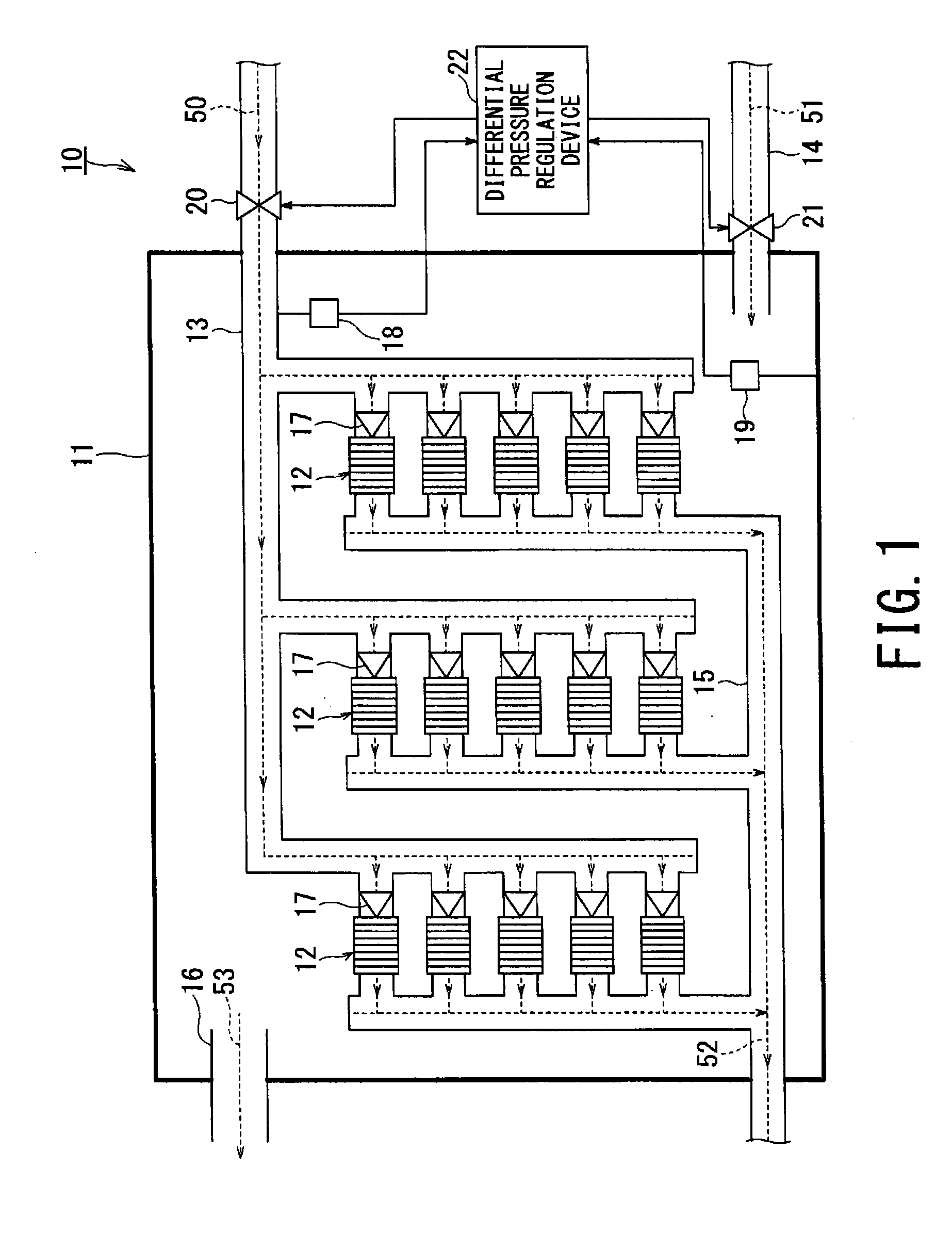
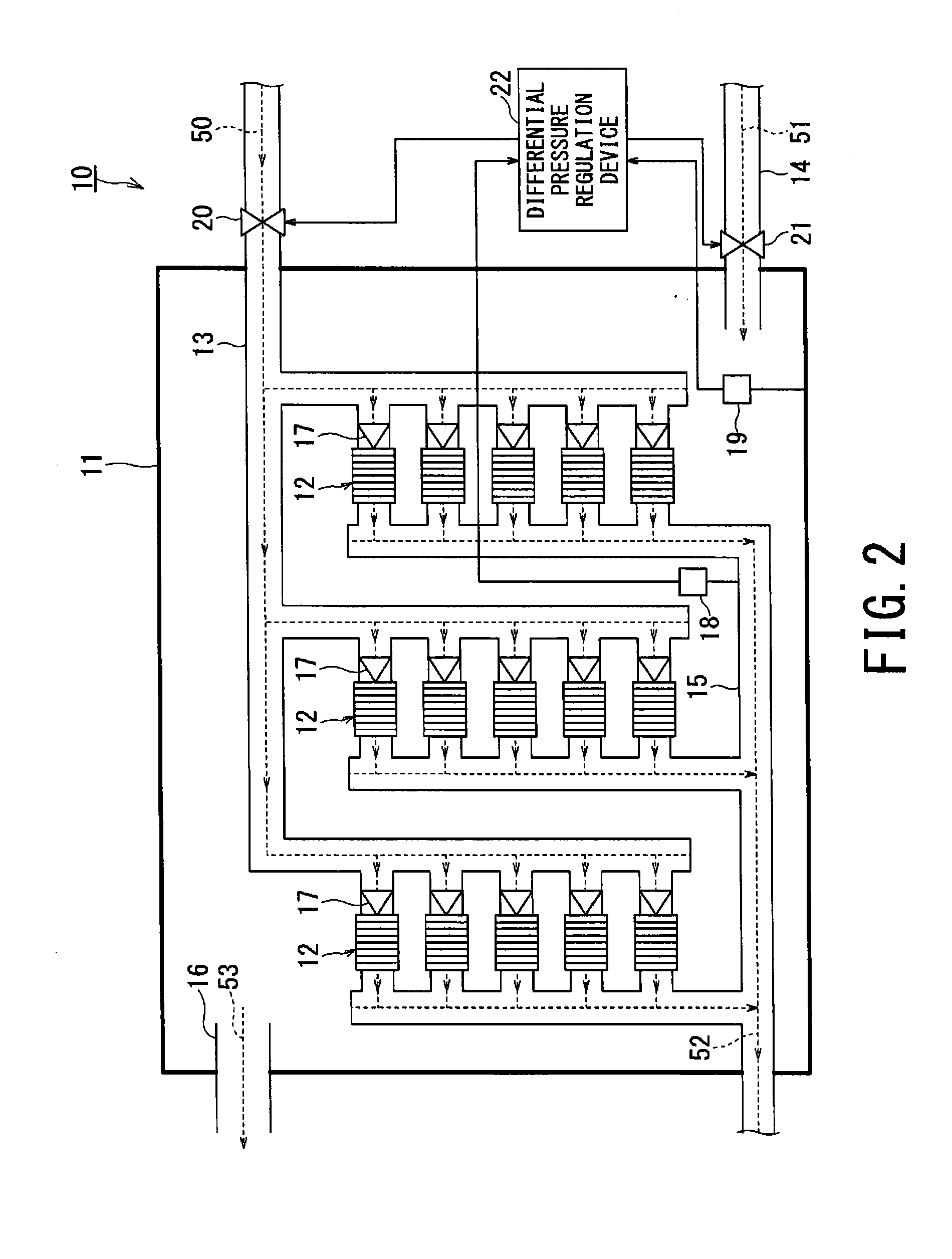
[0027]As shown in FIG. 1, a hydrogen production system 10 according to a first embodiment includes a plurality of cell stacks 12, a first flow path 13, a second flow path 14, and a flow regulation device 17. The plurality of cell stacks 12 are provided within a reaction containment 11, and generate hydrogen by high temperature steam electrolysis by supplying steam 50 into the plurality of cell stacks 12. The first flow path 13 guides the steam 50 to each of the cell stacks 12. The second flow path 14 causes carrier gas 51 containing air as a main component to flow into the reaction containment 11. The flow regulation device 17 is provided at an inlet of the steam 50 so as to regulate a flow rate of the steam 50 caused to flow into each of the cell stacks 12 to be uniform.

[0028]Although a configuration in which the first flow path 13 is branched and connected to five cell stacks 1...

second embodiment

[0054]FIG. 5 is a configuration diagram of the hydrogen production system 10 according to a second embodiment. Note that components and portions corresponding to those of the first embodiment (FIG. 1) are assigned same reference numerals, and an overlapping description is omitted.

[0055]A thermometer 25 is provided in the reaction containment 11, and measures an internal temperature of the reaction containment 11.

[0056]An internal heating device 23 is a heater that is provided on an inner peripheral surface of the reaction containment 11 to heat an inside of the reaction containment 11.

[0057]An external heating device 24 is a heater that is provided on an outer peripheral surface of the reaction containment 11 to heat the inside of the reaction containment 11.

[0058]The measured internal temperature of the reaction containment 11 is inputted into a temperature control device 26 from the thermometer 25. The temperature control device 26 determines whether or not the internal temperatur...

third embodiment

[0063]FIG. 7 is a configuration diagram of the hydrogen production system 10 according to a third embodiment. Note that a configuration of FIG. 7 is partially similar to that of FIG. 1, such as a configuration in which the steam 50 is caused to flow into the cell stacks 12 through the first flow path 13, and is thus shown and described in a simplified manner.

[0064]The cell stacks 12 are connected in parallel with a power supply 29 that applies a voltage to the cell stacks 12.

[0065]By connecting the cell stacks 12 in parallel with the power supply 29, an equal voltage is applied to the respective cell stacks 12, so that voltage control of the cell stacks 12 becomes easy. A configuration may be employed in which the plurality of cell stacks 12 are connected in series, and a plurality of rows of the cell stacks 12 connected in series are connected in parallel.

[0066]A ammeter 27 is a meter that measures a current flowing through each of the cell stacks 12 connected in parallel. FIG. 7 s...


PUM

PropertyMeasurementUnit
temperatureaaaaaaaaaa
flow rateaaaaaaaaaa

Abstract

A hydrogen production system that achieves highly-efficient hydrogen production even when hydrogen is produced by using the plurality of cell stacks is provided.A hydrogen production system includes a plurality of cell stacks provided within a reaction containment, the cell stacks generating hydrogen by high temperature steam electrolysis by supplying steam to the plurality of cell stacks, a first flow path guiding the steam to each of the cell stacks, a second flow path causing a carrier gas containing air as a main component to flow into the reaction containment, and a flow regulation device provided at an inlet of the steam in each of the cell stacks, the flow regulation device regulating a flow rate of the steam caused to flow into each of the cell stacks to be uniform.

Description

CROSS-REFERENCE TO RELATED APPLICATION[0001]This application is based upon and claims the benefit of priority from Japanese Patent application No. 2014-178087, filed on Sep. 2, 2014, the entire content of which is incorporated herein by reference.BACKGROUND OF THE INVENTION[0002]1. Field of the Invention[0003]Embodiments of the present invention relate to a field for producing hydrogen in which hydrogen is generated by using high temperature steam electrolysis.[0004]2. Related Art[0005]Realization of a hydrogen energy society using hydrogen as an energy medium has attracted attention. As one of technology for producing hydrogen, a high temperature steam electrolysis is widely known. The high temperature steam electrolysis is a method in which hydrogen and oxygen are generated by electrolyzing steam with a high temperature (normally, 500° C. or more).[0006]The method can advantageously reduce an amount of electricity required for electrolysis by electrolyzing steam under a high tempe...

Claims


Application Information

Patent Timeline
Patent Type & Authority Applications(United States)
IPC IPC(8): C25B15/02C25B1/04C25B9/18
CPCC25B15/02C25B9/18C25B1/04C25B15/08C25B9/00C25B9/70Y02E60/36
Inventor KAWAJIRI, YUKOWATANABE, HISAOYOSHIMURA, RYOJIFUJIWARA, SEIJIYAMAUCHI, HIROYUKIKOMAI, MASAFUMIYAMADA, MASAHIKOKAMEDA, TSUNEJIYOSHINO, MASATOASADA, TAKATOSHIKASAI, SHIGEO
Owner KK TOSHIBA
Why Eureka
Try Eureka