Flooring system having assembly clip and related method

a technology of assembly clip and floor, which is applied in the direction of flooring, building components, building repairs, etc., can solve the problems of affecting the yield of the floor, the gap between adjacent flooring pieces, and the floor is not a simple material, and achieves the effect of improving the yield and being relatively inexpensive to manufactur

Active Publication Date: 2016-03-03
STOVER EVAN J +1
View PDF1 Cites 21 Cited by
  • Summary
  • Abstract
  • Description
  • Claims
  • Application Information

AI Technical Summary

Benefits of technology

[0016]Another advantage is that the herein described fastening clip is durable and relatively inexpensive to manufacture.
[0017]Yet another advantage realized is the ability to incorporate flooring components made from different materials (i.e., solid hardwood and marble) into a single continuous floor despite these components having widely different physical and mechanical properties.
[0018]Still another advantage is that the herein described flooring system does not require special equipment typically used in hardwood flooring installation, such as flooring nail guns and flooring jacks.
[0019]Yet another advantage provided is that flooring installation using the

Problems solved by technology

However, wood is not a simple material, at least for purposes of fabrication.
Resulting unequal dimensional changes can lead to several problems or issues during the service life of wood floors.
These issues can include crowning or cupping of individual flooring pieces, gapping between adjacent flooring pieces, and localized or widespread heaving of the floor, among others.
While this technique has been made possible with engineered laminate and composite wood floors, success has not been achieved with solid wood due t

Method used


Image

  • Flooring system having assembly clip and related method
  • Flooring system having assembly clip and related method
  • Flooring system having assembly clip and related method

Examples


Embodiment Construction

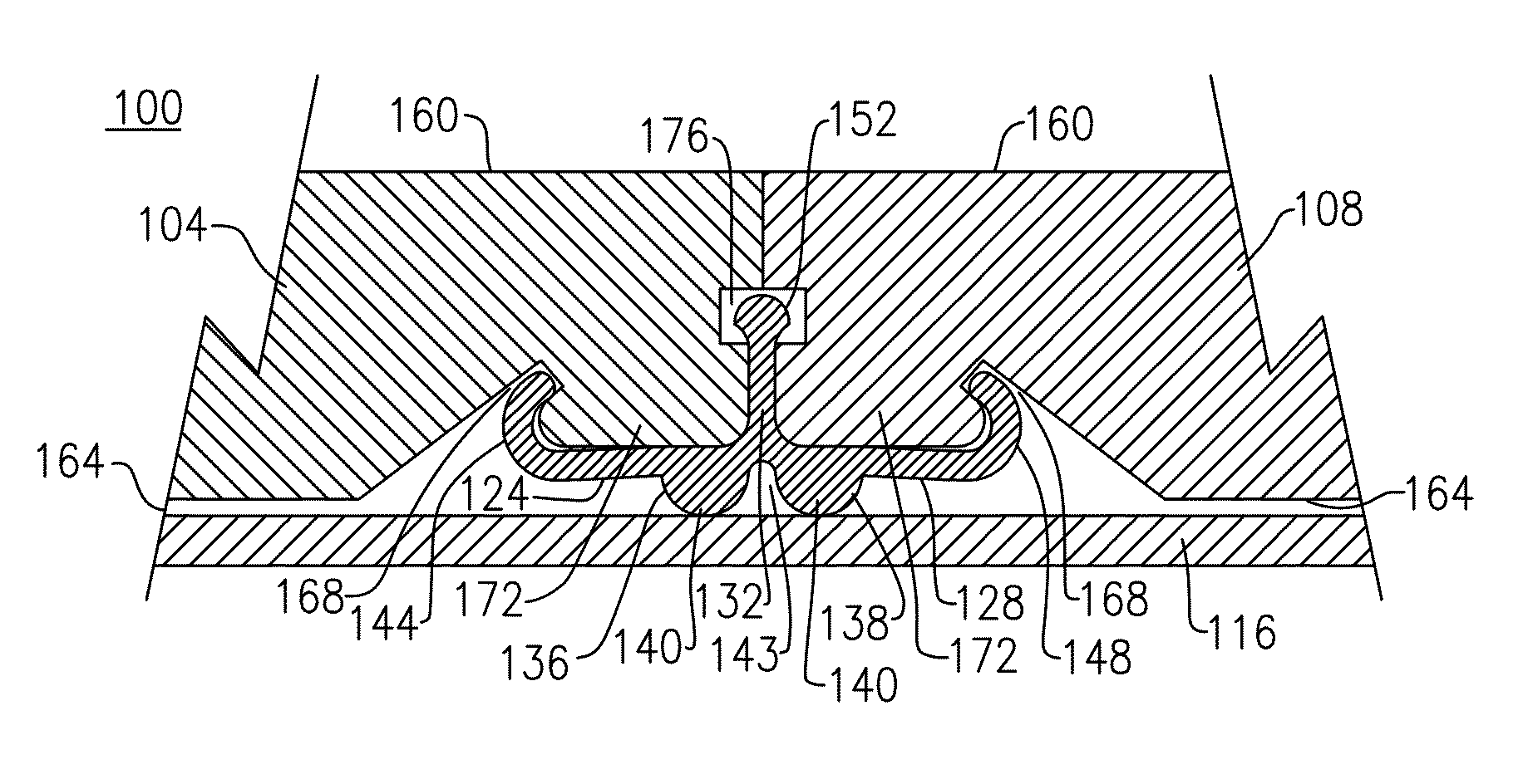
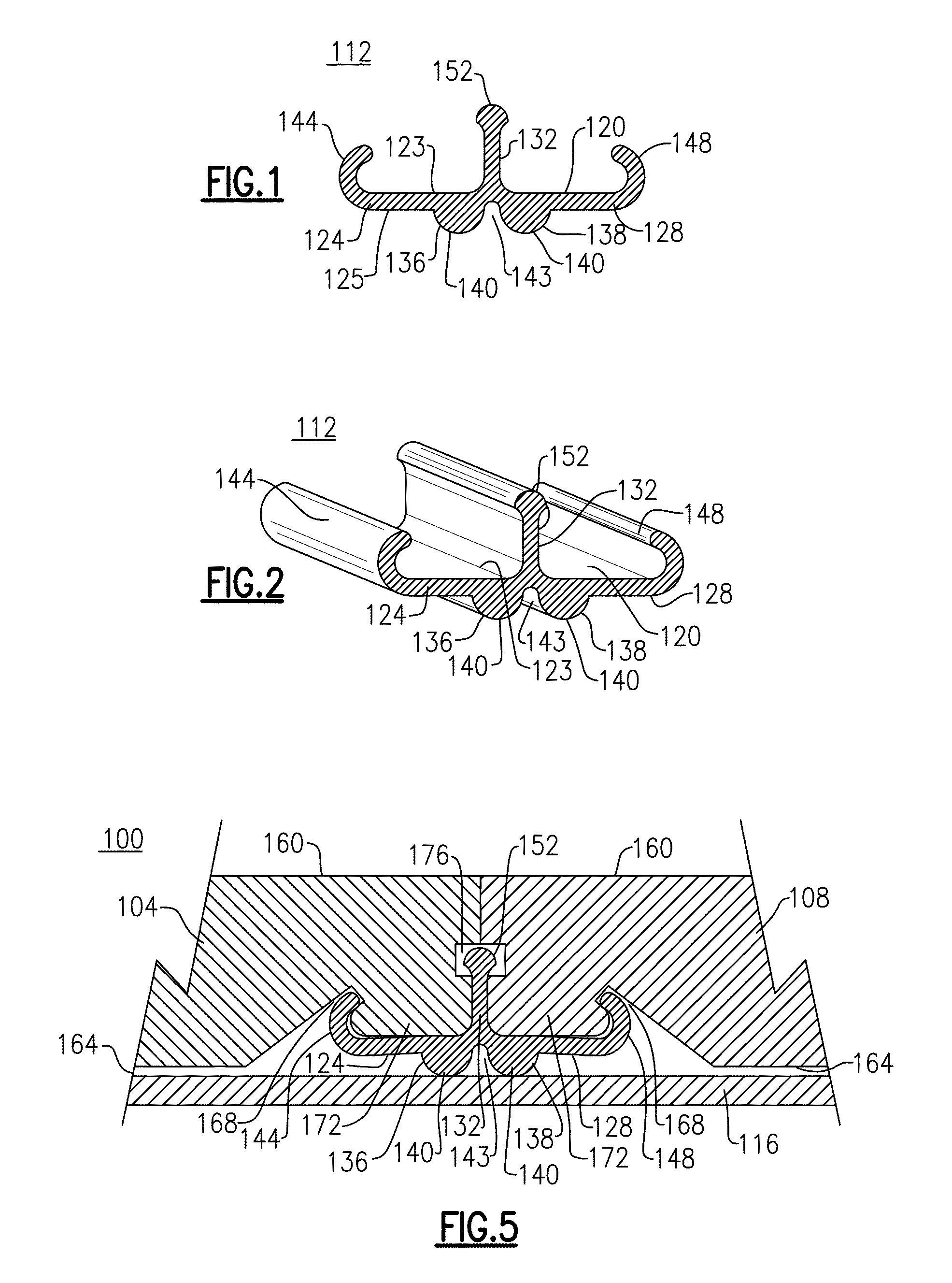
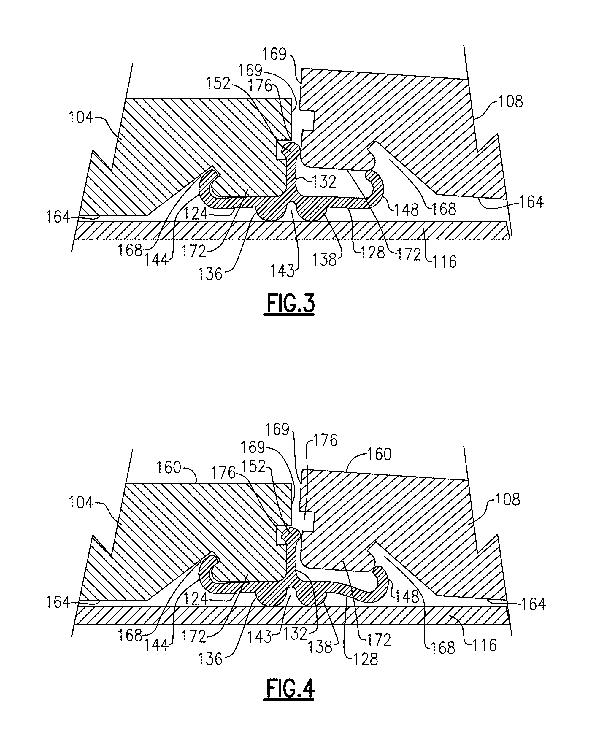
[0030]The following relates to exemplary embodiments of a sub-flooring system (also herein referred to as a “floating floor”), including an floor panel connector (also synonymously referred to throughout as an “assembly clip”, or “assembly connector”) that is configured to secure together a pair of floor components (i.e., floor panels) onto a supporting surface or substrate. It will be readily apparent that other variations and modifications can be contemplated by a person of sufficient skill that further embodies the inventive ambits which are described herein. Throughout the course of discussion, a number of descriptive terms are used in order to provide a suitable frame of reference with regard to the accompanying drawings. These terms, which may include “outer”, “inner”, “internal”, “external”, “above”, “below”, “top”, “beneath”, and the like are not intended to otherwise limit the effective scope of this application, including the appended claims, unless so specifically indicat...


PUM


Abstract

A flooring system includes a plurality of individual flooring pieces, such as floor panels, each having a wear surface, an opposing mounting surface and a retention groove disposed within the mounting surface. A floor panel connector used to interconnect at least two of the floor panels has a base, at least one mast extending from an upper surface of the base and a pair of flexible arms. Each flexible arm extends transversely from opposing sides of the at least one mast and has an extending end. Contacting portions extending from a lower surface of the base are configured to engage the support surface and create a spacing between each flexible arm and the support surface to permit each flexible arm to elastically deflect toward the support surface when pressure is exerted on a floor panel. This deflection enables the extending end of each flexible arm to engage the retention groove of a corresponding floor panel.

Description

CROSS REFERENCE TO RELATED APPLICATIONS[0001]This application claims priority under relevant portions of 35 U.S.C. §119 to U.S. Patent Application No. 62 / 042,466, filed Aug. 27, 2014 and entitled: Dynamic Floating Floor Assembly Clip. The entire contents of this referenced application is herein incorporated by reference.TECHNICAL FIELD[0002]This application relates generally to the field of building construction, and more specifically to a flooring system that includes complementary fastening clips and a related construction method using same.BACKGROUND[0003]Wood floors are a durable and elegant flooring option for purposes of either constructing or remodeling an interior space. However, wood is not a simple material, at least for purposes of fabrication. That is, wood is both hydroscopic and anisotropic. As is generally known, the term “hydroscopic” means that wood will readily exchange water with its surroundings, in which any gain or loss of water can result in dimensional change...

Claims


Application Information

Patent Timeline
IPC IPC(8): E04F15/02
CPCE04F15/02044E04F2201/0517E04F2201/0146E04F2015/0205E04F15/02016E04F15/02022E04F15/04E04F2015/02116E04F2201/0511
Inventor STOVER, EVAN, J.STOVER, LEE, R.
Owner STOVER EVAN J
Why Eureka
Try Eureka