Ceramic heater

a ceramic heater and heater body technology, applied in the field of ceramic heaters, can solve the problems of difficult to achieve an improvement in long-term reliability, localized unusual heat generation, and the like of the feeder line being subject to cracking or the lik

Active Publication Date: 2016-03-03
KYOCERA CORP
View PDF4 Cites 111 Cited by
  • Summary
  • Abstract
  • Description
  • Claims
  • Application Information

AI Technical Summary

Problems solved by technology

However, in the ceramic heater disclosed in Patent Literature 1, the possibility arises that due to repeated use in a high-temperature environment the feeder line will be subject to cracking or the like.
This causes changes in the resistance value of the feeder line, which may lead to localized unusual heat generation.
As a consequence, it is difficult to achieve an improvement in long-term reliability for the case of using the ceramic heater repeatedly in a high-temperature environment.

Method used


Image

  • Ceramic heater
  • Ceramic heater
  • Ceramic heater

Examples


examples

[0050]A ceramic heater was produced by way of an example of the invention in the following manner.

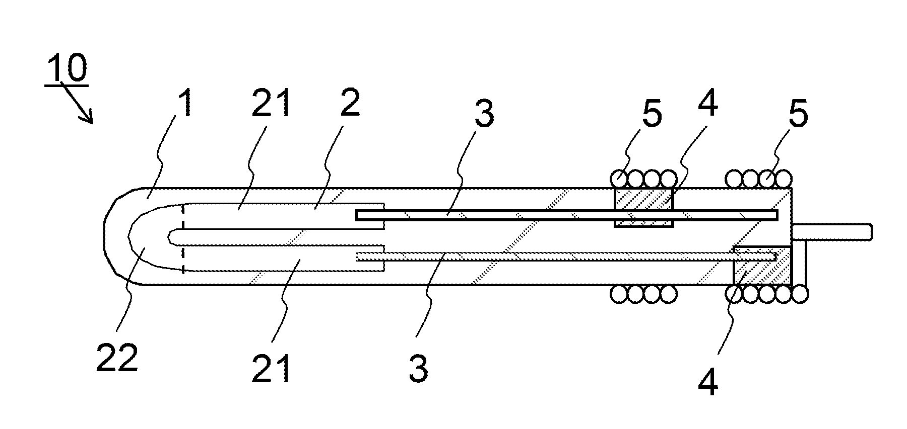
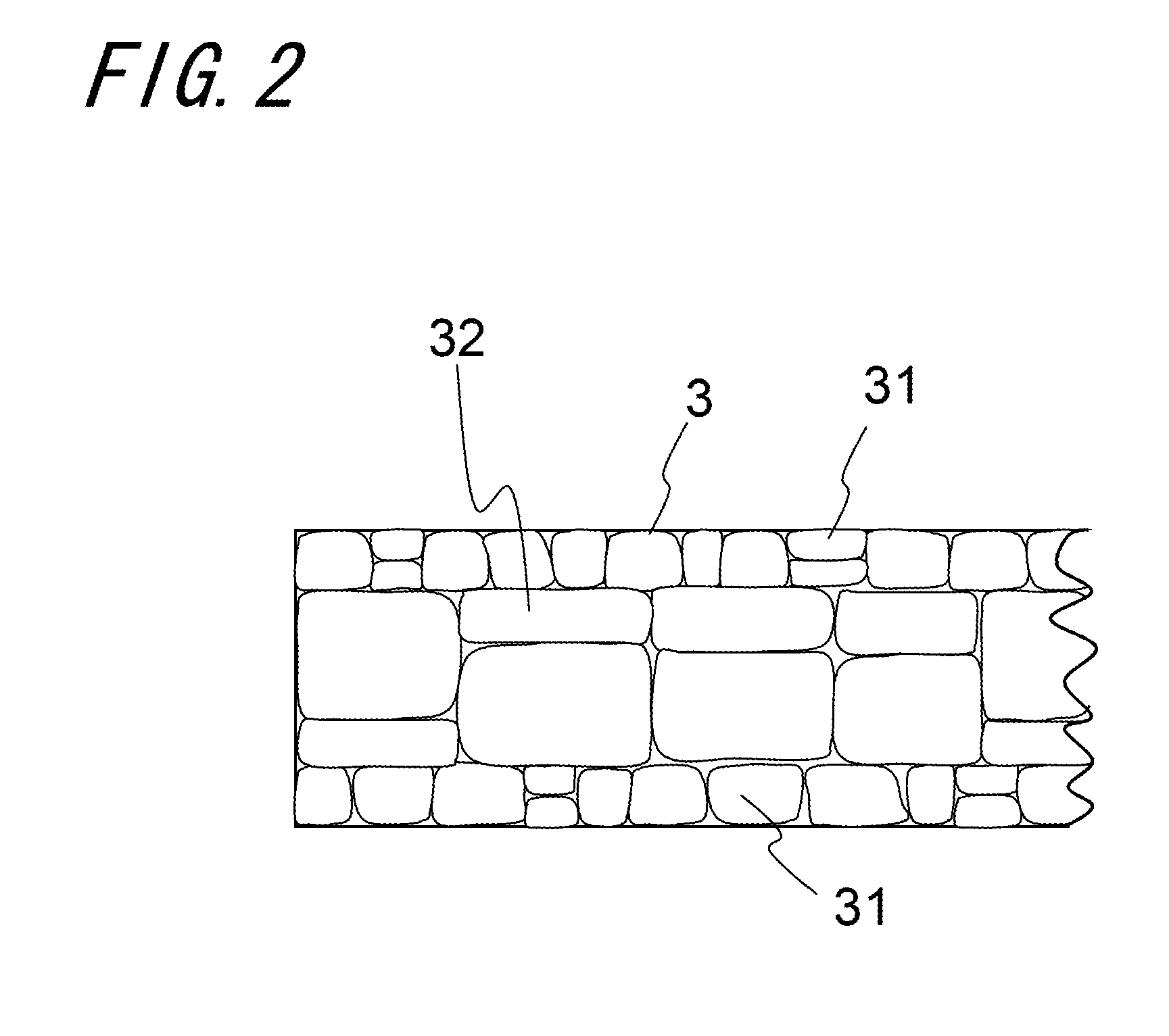
[0051]To begin with, raw material powder was prepared by mixing silicon nitride powder, which is a raw material for constituting the ceramic structure 1, in an amount of 85% by mass with sintering aids, namely Yb2O3 powder in an amount of 10% by mass, MoSi2 powder in an amount of 3.5% by mass, and aluminum oxide powder in an amount of 1.5% by mass. After that, the first molded body and the second molded body that constitute the ceramic structure 1 were prepared using the raw material powder by means of pressure molding. At this time, 100 ppm K2O content was imparted to the binder used for the silicon nitride powder.

[0052]Next, an electrically conductive paste for constituting the heat-generating resistor 2 and the electrode extraction portion 4 was prepared by mixing tungsten carbide (WC) powder in an amount of 70% by mass with the raw material powder in an amount of 30% by mass, and th...


PUM

PropertyMeasurementUnit
temperatureaaaaaaaaaa
diameteraaaaaaaaaa
lengthaaaaaaaaaa

Abstract

A ceramic heater of the invention includes a ceramic structure; a heat-generating resistor embedded in the ceramic structure; and a feeder line embedded in the ceramic structure so as to be connected, at one end thereof, to the heat-generating resistor. The feeder line is made of metal, and metal grains of a center region of the feeder line are greater in grain size than metal grains of an outer periphery region of the feeder line. Even if a crack developed in the outer periphery region of the feeder line propagates through grain boundaries in the outer periphery region and comes near the center region, propagation of the crack through the interior of the center region can be suppressed.

Description

TECHNICAL FIELD[0001]The present invention relates to a ceramic heater.BACKGROUND ART[0002]Ceramic heaters are known as heaters for use in, for example, a vehicle-mounted heating system, an oil fan heater, or a glow plug of an automotive engine. For example, in Japanese Unexamined Patent Publication JP-A 2000-156275 (hereafter referred to as “Patent Literature 1”), there is disclosed an example of the ceramic heaters.[0003]The ceramic heater disclosed in Patent Literature 1 comprises: a ceramic structure; a heat-generating resistor embedded in the ceramic structure; and a feeder line embedded in the ceramic structure so as to be connected to the heat-generating resistor.[0004]However, in the ceramic heater disclosed in Patent Literature 1, the possibility arises that due to repeated use in a high-temperature environment the feeder line will be subject to cracking or the like. This causes changes in the resistance value of the feeder line, which may lead to localized unusual heat gen...

Claims


Application Information

Patent Timeline
Patent Type & Authority Applications(United States)
IPC IPC(8): F23Q7/00F23Q7/22H05B3/18H05B3/28
CPCH05B3/12H05B3/48H05B2203/027F23Q7/001H05B3/18H05B3/283F23Q7/22
Inventor KOBAYASHI, AKIO
Owner KYOCERA CORP
Why Eureka
Try Eureka