Solar array support methods and systems

a solar array and support method technology, applied in the field of solar energy capture, can solve the problems of difficult and expensive implementation of solar panel arrays in remote locations, difficult and expensive solar panel array installation in environmentally sensitive areas without significantly affecting the surrounding habitat, and the number of anchor lines used is reduced, so as to minimize the number of anchor lines used, the effect of reducing construction efforts and maintenance needs of the system

Inactive Publication Date: 2016-03-03
P4P HLDG
View PDF0 Cites 31 Cited by
  • Summary
  • Abstract
  • Description
  • Claims
  • Application Information

AI Technical Summary

Benefits of technology

[0023]As set forth in the first embodiment, one particular advantage of the present invention is the ability to provide a solar array support system and method in which a minimum amount of materials are required. Consequently, reduced labor is required for installation. The support system and method provide a solution for supporting solar arrays in a very cost-effective, yet structurally sound and reliable manner.
[0024]One particularly advantageous arrangement of support elements in accordance with the present invention is a ground mounted system in which an array of photovoltaic panels are supported by (i) four columns, one column located at each corner of the array, (ii) first and second main cables that suspend the solar panels at an inclined angle, and (iii) a pair of longitudinal anchor lines located at opposite ends of the array. This minimum arrangement of structural elements provides an extremely efficient, yet structurally sufficient support for a solar panel array. Accordingly, the system also minimizes construction efforts as well as maintenance needs of the system.
[0025]In this simplified support system, the columns are anchored in the ground so that the columns act as vertical cantilever supports that can withstand bending moments in all directions. Preferably, there are a pair of short columns and a pair of tall columns that provide the desired angularity with respect to how the solar panels are disposed for capture of sunlight. This angularity also serves to allow drainage of liquid from the solar panels without a separate drain system. The pairs of longitudinal anchor lines provide additional structural stability, yet minimize the number of anchor lines used.
[0026]From this simplified arrangement of structural support elements, additional structural support can be provided by adding additional anchor lines, cables, and columns as set forth in the other embodiments of the present invention.
[0027]With respect to minimizing structural requirements for the solar panel receivers or pods that secure the solar panels, as also set forth in the first embodiment, the method and system of the invention contemplate utilization of the minimum number of struts to support the solar panels. One simplified arrangement for the struts includes a pair of main transverse struts that extend substantially perpendicular to and mounted to the first and second main cables. A pair of longitudinal struts may interconnect the transverse struts. Cable receivers are used to mount the cables to the main struts. Connecting brackets are used to secure the solar panels to the main struts. In this simplified pod construction, adequate structural support is provided to minimize torsional and bending forces, which could otherwise damage the solar panels; yet the number of structural elements is minimized to reduce construction costs and labor costs.
[0028]Further advantages and features of the systems and methods of the present invention will become apparent from a review of the following figures, along with the detailed description.

Problems solved by technology

Present systems for supporting solar panels tend to be bulky and expensive.
Given the size and weight of such systems, implementation of solar panel arrays in remote locations is difficult and expensive.
When large equipment is required, installation of a solar panel array in an environmentally sensitive area without significantly impacting the surrounding habitat becomes very difficult.
Typically, such support systems do not allow for secondary uses of the solar panel arrays.

Method used


Image

  • Solar array support methods and systems
  • Solar array support methods and systems
  • Solar array support methods and systems

Examples


Embodiment Construction

[0197]The following detailed description should be read with reference to the drawings. The drawings, which are not necessarily to scale, depict illustrative embodiments and are not intended to limit the scope of the invention.

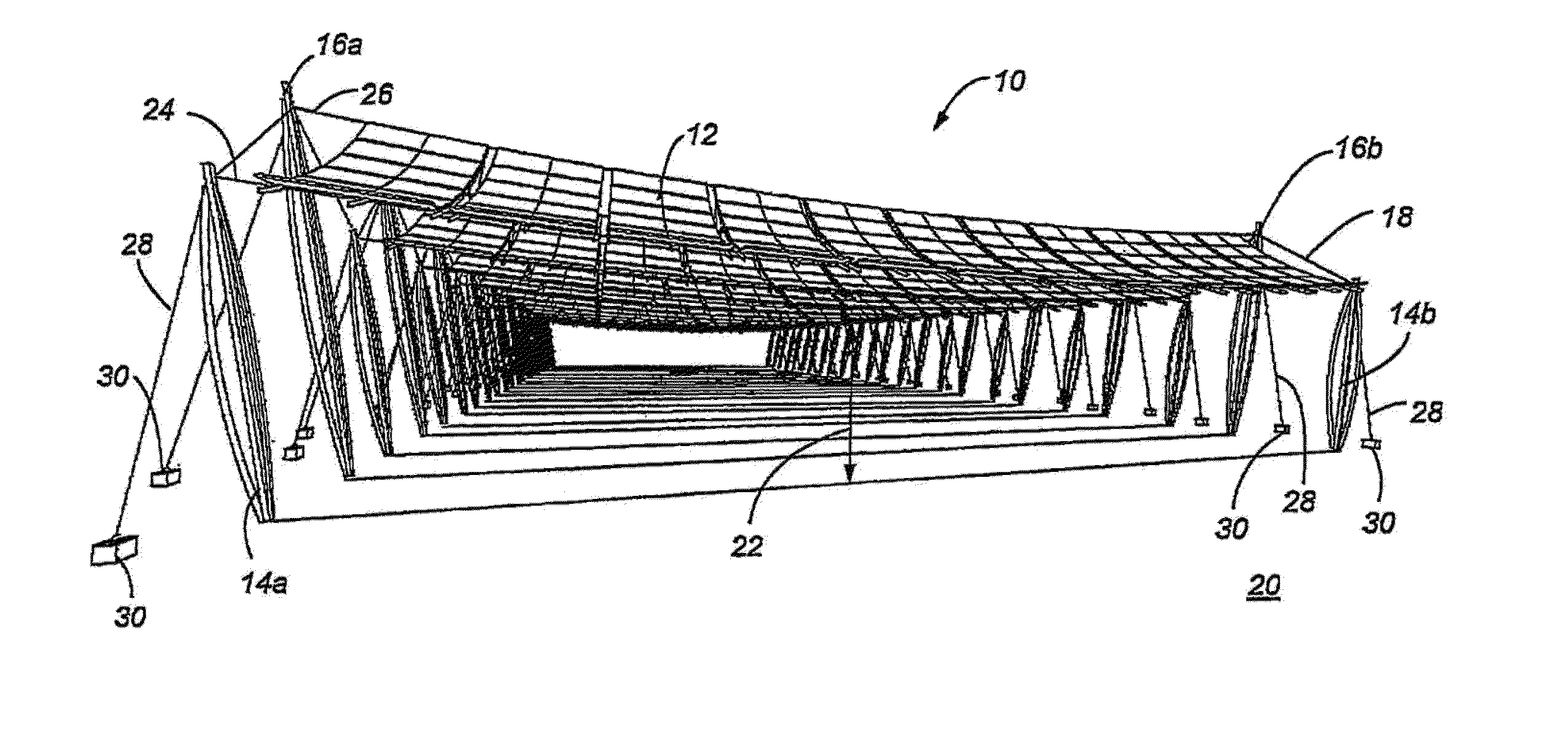
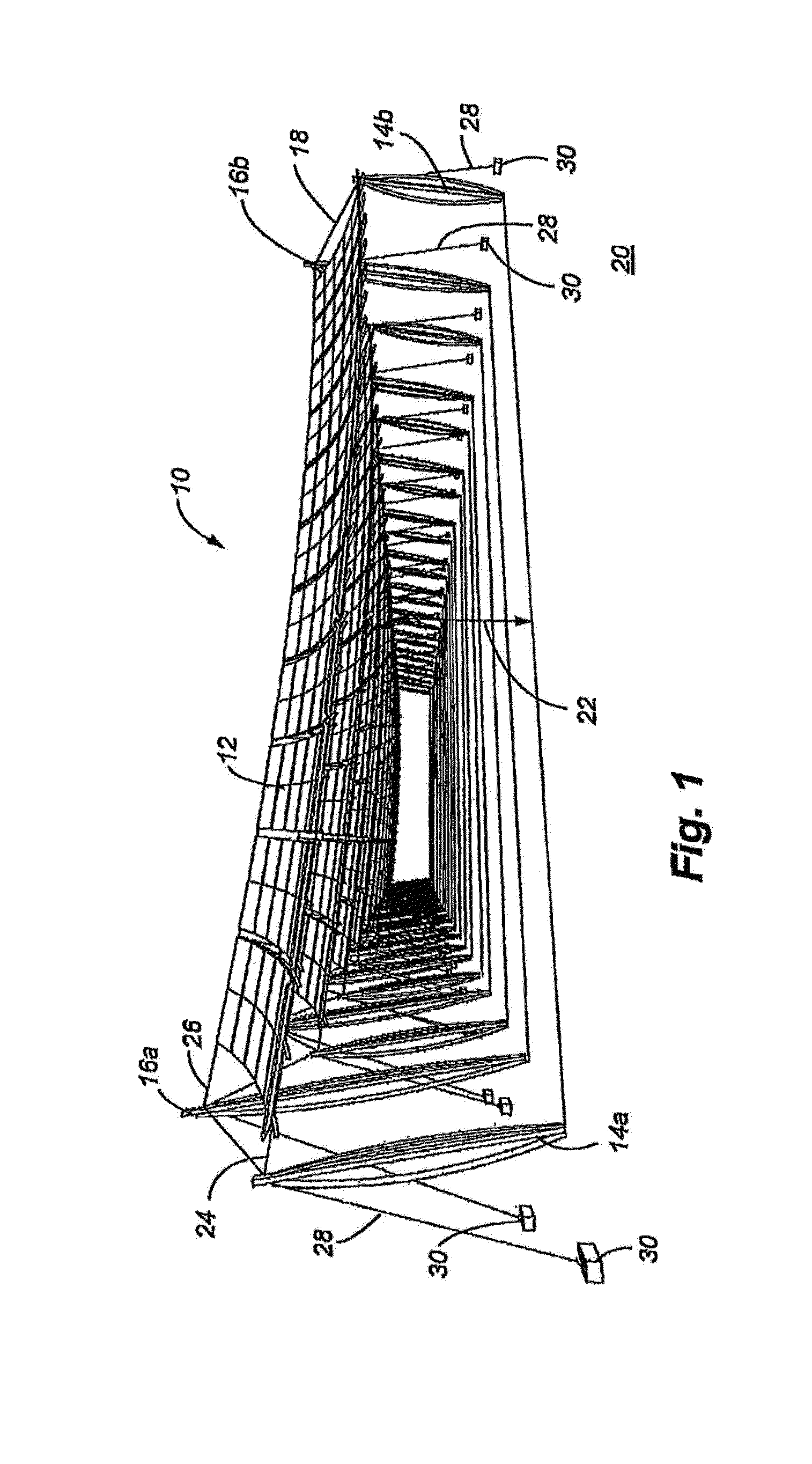
[0198]FIG. 1 is a perspective view of a solar panel array supported in accordance with an illustrative embodiment. A solar panel array 10 is illustrated as including a number of solar panel receivers or pods 12. Pairs of short columns 14a, 14b and tall columns 16a, 16b are aligned with one another. The pairs of columns 14a, 16a and 14b, 16b may also be connected by a stability cable 18 that runs along the edges of the array 10. The solar panel receivers 12 are held above a surface 20 at a height 22 defined by the columns 14a, 14b, 16a, 16b. A first main cable 24 is suspended between the short columns 14a, 14b, and a second main cable 26 is suspended between the tall columns 16a, 16b. The solar panel receivers 12 are designed to be supported by the cables 24, 2...


PUM


Abstract

Systems and methods for disposing and supporting a solar panel array are disclosed. The embodiments comprise various combinations of cables, support columns, and pod constructions in which to support solar panels. Special installations of the system can include systems mounted over structures such as parking lots, roads, aqueducts, and other bodies of water. Simplified support systems with a minimum number of structural elements can be used to create effective support for solar panel arrays of varying size and shapes. These simplified systems minimize material requirements and labor for installation of the systems.

Description

CROSS REFERENCE TO RELATED APPLICATIONS[0001]This application is a continuation-in-part of U.S. application Ser. No. 14 / 738,499, filed on Jun. 12, 2015, which is a continuation of U.S. application Ser. No. 14 / 523,592, filed on Oct. 24, 2014, which is a continuation of U.S. application Ser. No. 14 / 092,612, filed on Nov. 27, 2013, which is a continuation of U.S. application Ser. No. 12 / 817,063 filed on Jun. 16, 2010, which is a continuation-in-part of U.S. application Ser. No. 12 / 580,170 filed on Oct. 15, 2009, which is a continuation-in-part application of U.S. application Ser. No. 12 / 466,331, filed on May 14, 2009, which is a continuation-in-part application of U.S. application Ser. No. 12 / 255,178, filed on Oct. 21, 2008, which is a continuation-in-part application of U.S. application Ser. No. 12 / 143,624, filed on Jun. 20, 2008, which is a continuation-in-part application of U.S. application Ser. No. 12 / 122,228, filed on May 16, 2008, entitled “Solar Array Support Methods and System...

Claims


Application Information

Patent Timeline
Patent Type & Authority Applications(United States)
IPC IPC(8): H02S20/10
CPCH02S20/10Y02E10/47H02S20/20F24J2/5241H02S20/32E04C3/30E04C3/32E04C3/34F24S25/10F24S25/50Y02E10/50
Inventor CONGER, STEVEN, J.
Owner P4P HLDG
Why Eureka
Try Eureka