Internal combustion engine ignition device and ignition method

Active Publication Date: 2016-03-10
NISSAN MOTOR CO LTD
View PDF4 Cites 2 Cited by
  • Summary
  • Abstract
  • Description
  • Claims
  • Application Information

AI Technical Summary

Benefits of technology

The invention aims to prevent damage to a spark plug caused by pre-ignition in an operating region where the air-fuel mixture is highly ignitionable. In this region, a shorter energization time for the primary coil is set to avoid pre-ignition and damage to the spark plug. The invention allows for a relatively high discharge energy to be supplied in all operating regions, except for the low-speed high-load region where pre-ignition is most likely to occur. This ensures reliable ignition even in hard-to-flammable regions, such as combustion with a large amount of exhaust gas recirculation.

Problems solved by technology

That is, an operating region, in which pre-ignition that causes no-discharge may possibly occur, is limited to a specified low-speed high-load region.

Method used


Image

  • Internal combustion engine ignition device and ignition method
  • Internal combustion engine ignition device and ignition method
  • Internal combustion engine ignition device and ignition method

Examples


Embodiment Construction

[0023]One embodiment of the present invention is hereinafter described in detail with reference to the drawings.

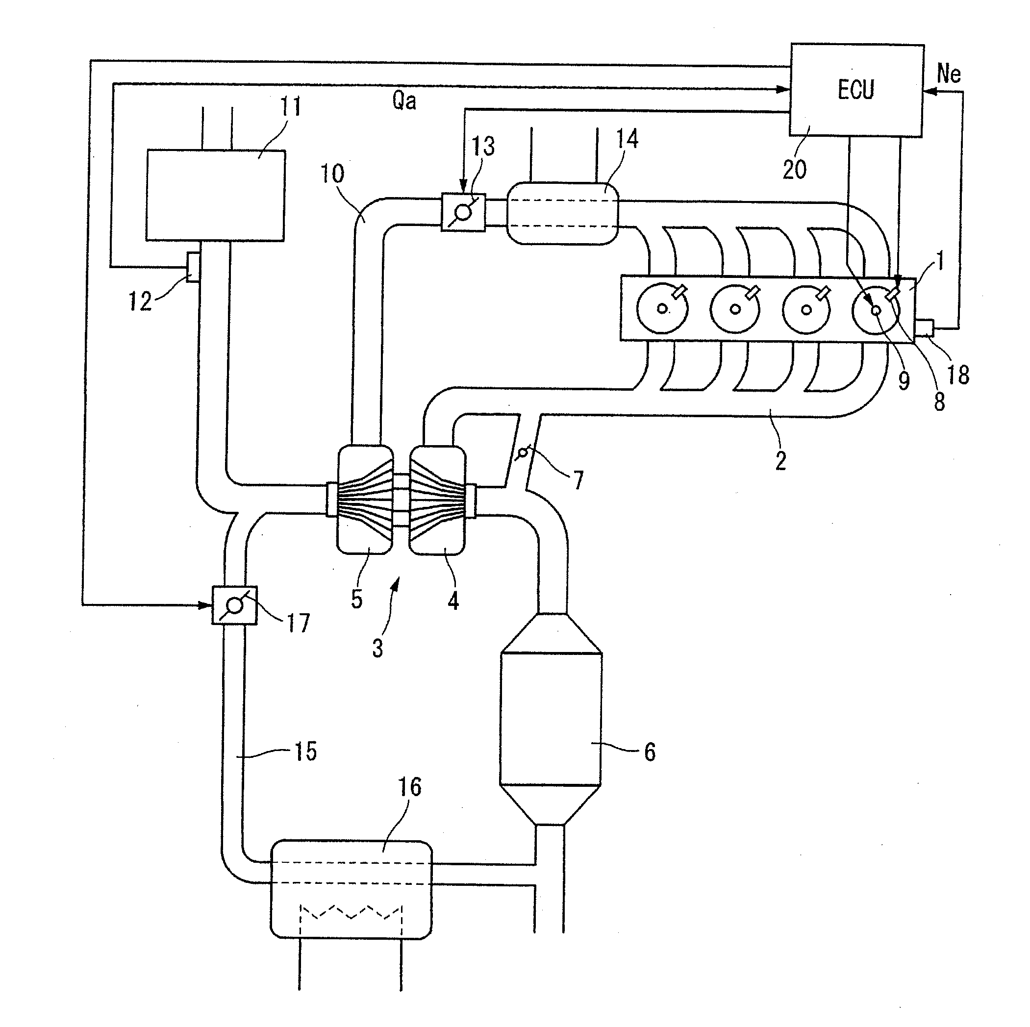
[0024]FIG. 1 shows an exhaust gas recirculation (EGR) device equipped supercharged engine as one example of an internal combustion engine 1 to which the ignition device of the invention is applied. An exhaust turbine 4 of a turbo supercharger 3 is placed in an exhaust passage 2 of internal combustion engine 1 that is a gasoline engine. A three-way catalytic converter 6 is disposed on the downstream side of the exhaust turbine. An exhaust muffler (not shown) is further arranged on the downstream side of exhaust passage 2. Exhaust passage 2 is opened through the exhaust muffler to the outside. The aforementioned exhaust turbine 4 is equipped with a well-known waste gate valve 7 for supercharging pressure control. In the shown embodiment, internal combustion engine 1 is constructed by an in-cylinder direct-injection type. A fuel injection valve 8 which injects fuel into a cyl...


PUM


Abstract

When an operating condition including load and speed of an internal combustion engine is in a prescribed low-speed high-load region, i.e., an energy suppression region, having a possibility causing pre-ignition, energization time TDWLMIN for the energy suppression region is selected as a primary coil energization time. In other normal regions, normal energization time TDWL is selected. Normal energization time TDWL has a characteristic such that the normal energization time shortens, as the engine speed increases. In a low speed region, a given energization time that can fulfil a discharge energy required in a high exhaust gas recirculation region is provided. Energization time TDWLMIN for the energy suppression region is constant regardless of engine speeds and relatively short, and is set to a level such that a coil generated maximum voltage does not exceed a withstand voltage of a spark plug even when no-discharge occurs due to pre-ignition.

Description

TECHNICAL FIELD[0001]The present invention relates to an internal combustion engine ignition device and ignition method using an ignition coil including a primary coil and a secondary coil.BACKGROUND ART[0002]On ignition devices using an ignition coil, a high discharge voltage is produced or induced in a secondary coil by interrupting primary current at predetermined ignition timing after having energized the primary current to the primary coil, thus generating an electric discharge between the opposing electrodes of a spark plug connected to the secondary coil. Basically, the discharge voltage and discharge energy induced in the secondary coil correlates with the primary coil energization time (see FIG. 6).[0003]The aforementioned primary coil energization time, which influences the discharge energy, is generally determined by engine revolution speed. Conventionally, the lower the engine speed, the longer the energization time. However, Patent document 1 teaches that the energizati...

Claims


Application Information

Patent Timeline
IPC IPC(8): F02P9/00
CPCF02P9/002F02P5/152F02P5/1528F02P3/053Y02T10/40F02P3/045
Inventor SHIRAISHI, TAISUKEKASSAI, MASAHARU
Owner NISSAN MOTOR CO LTD
Why Eureka
Try Eureka