Crankshaft isolating pulley

a crankshaft and isolating technology, applied in the direction of shock absorbers, mechanical instruments, inertia effect dampers, etc., can solve the problems of reducing the operating life of belts, often experiencing belt chirp noise in the engine accessory drive system,

Active Publication Date: 2016-03-10
THE GATES CORP
View PDF37 Cites 13 Cited by
  • Summary
  • Abstract
  • Description
  • Claims
  • Application Information

AI Technical Summary

Problems solved by technology

Due to increased crankshaft vibration plus high acceleration/deceleration rates and high alternator inertia the engine ...

Method used


Image

  • Crankshaft isolating pulley
  • Crankshaft isolating pulley
  • Crankshaft isolating pulley

Examples


Embodiment Construction

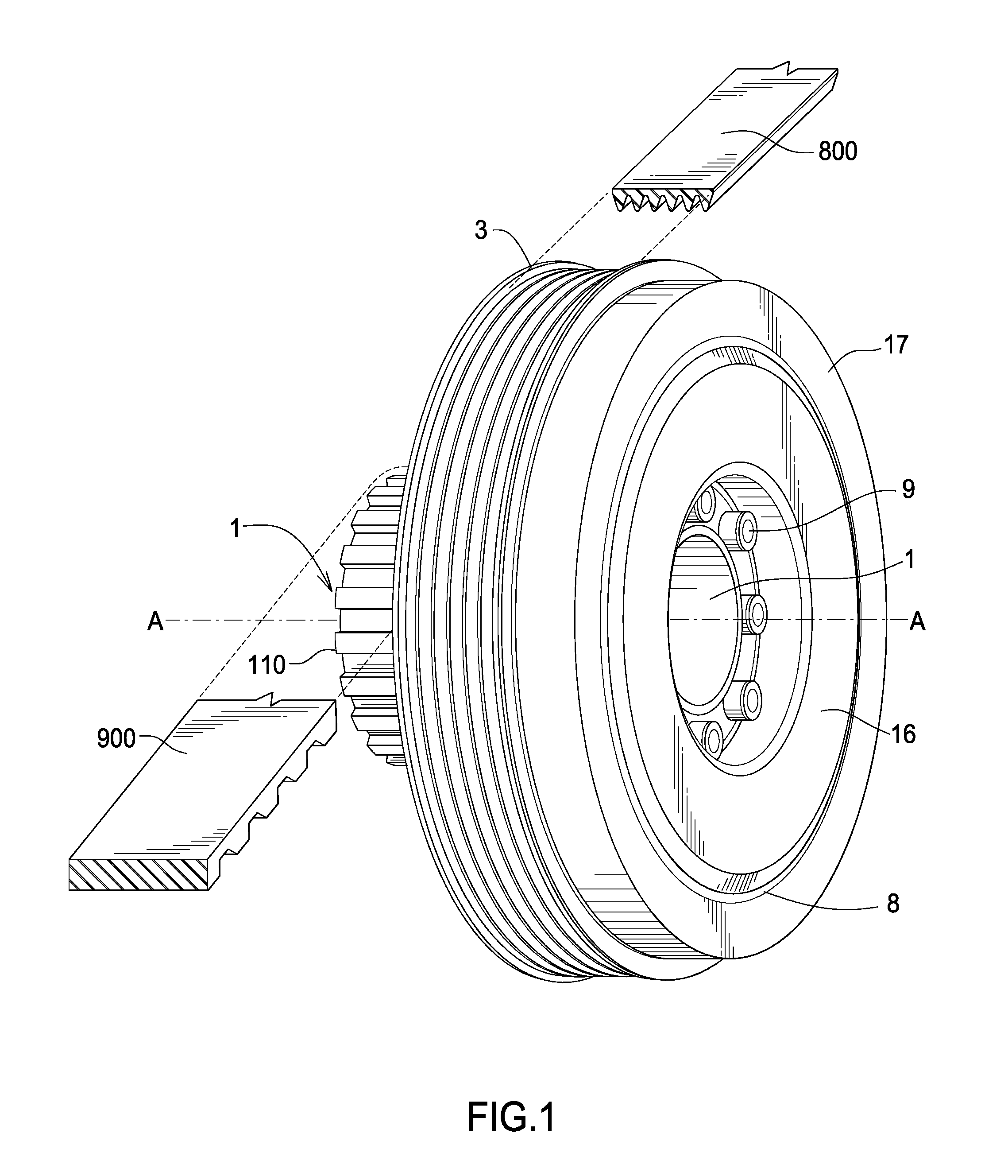
[0025]FIG. 1 is a front perspective view of the inventive device. The device is typically attached to the crankshaft of an internal combustion engine (not shown).

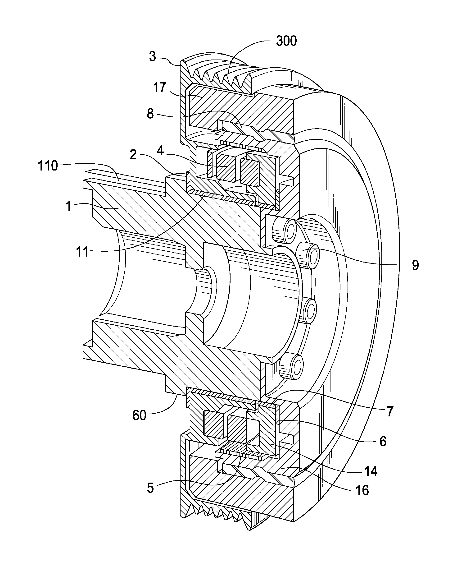
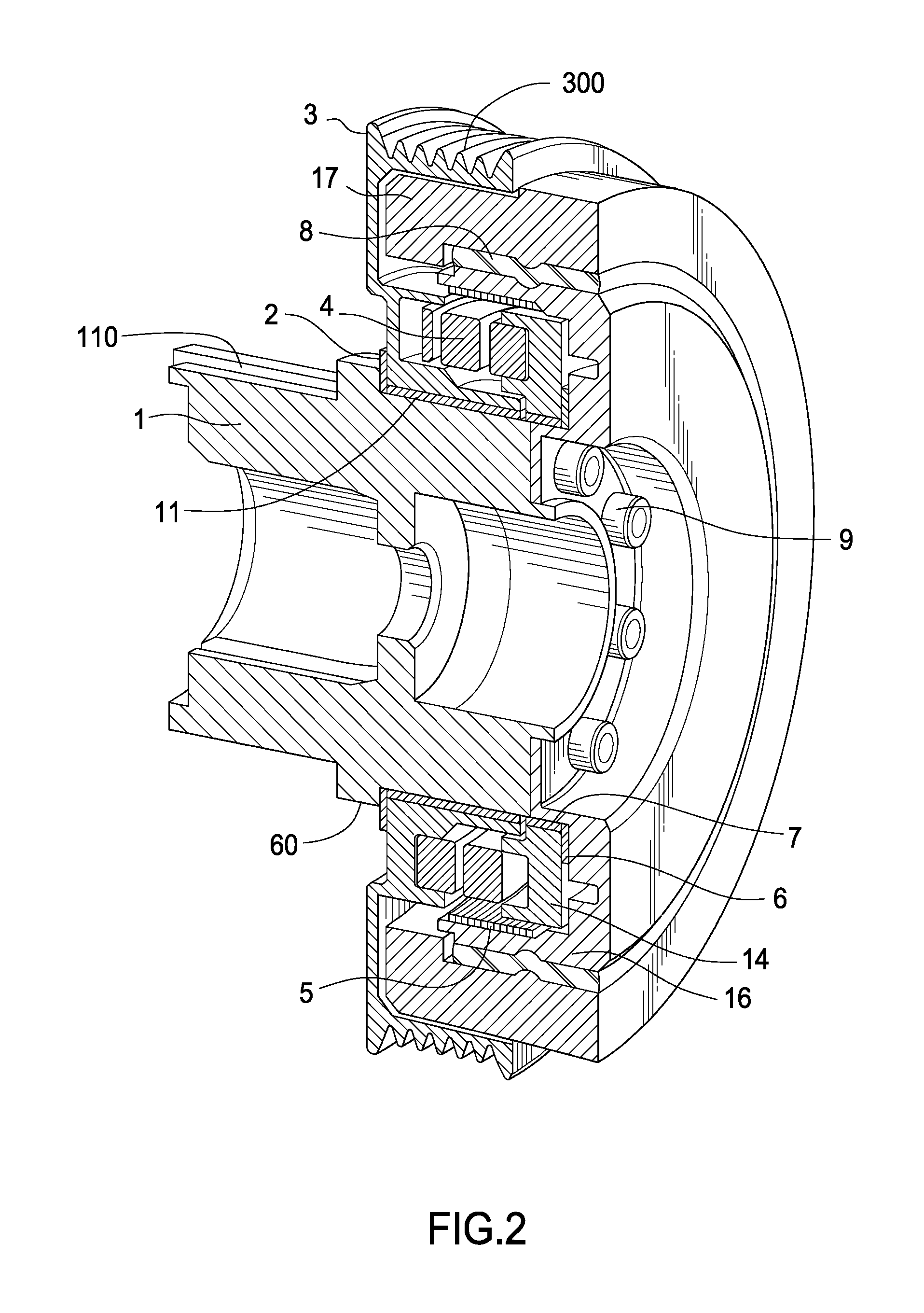
[0026]FIG. 2 is a cross-section view of the device. The inventive device comprises hub 1. Hub 1 further comprises a crankshaft sprocket 110 having a toothed surface. Crankshaft sprocket 110 can be used to drive an engine timing belt 900. Timing belt 900 is referred to as a toothed or synchronous belt.

[0027]Thrust bearing 2 engages shoulder 60 on hub 1. Pulley 3 is journalled to hub 1 on bushing 11. Pulley 3 comprises a profile 300 for engaging a multi-ribbed belt 800. The multi-ribbed belt may be used to drive an engine accessory system (not shown). Spring 4 is engaged between pulley 3 and spring carrier 14. Clutch spring 5 is engaged between spring carrier 14 and inertia carrier 16. Spring carrier 14 bears upon thrust bearing 6. Spring carrier 14 is journalled to hub 1 upon bushing 7. Inertia mass 17 is mounted to inertia ...


PUM


Abstract

An isolating pulley comprising a hub comprising an inertia carrier, the inertia carrier having an inner surface, a spring carrier journalled to the hub, the spring carrier having a releasable driving engagement with the inertia carrier, a pulley journalled to the hub, a spring drivingly engaged between the spring carrier and the pulley, a clutch spring having a frictional engagement with the inner surface, and which frictional engagement is partially releasable upon a temporary, pressing contact of the pulley upon the clutch spring.

Description

FIELD OF THE INVENTION[0001]The invention relates to an isolating pulley, and more particularly, to an isolating pulley having a clutch spring releasably engaged with an inertia carrier inner surface upon a pressing contact of the pulley with the clutch spring.BACKGROUND OF THE INVENTION[0002]Diesel engine use for passenger car applications is increasing due to the benefit of better fuel economy. Further, gasoline engines are increasing compression ratios to improve the fuel efficiency. As a result, diesel and gasoline engine accessory drive systems have to overcome the vibrations of greater magnitude from crankshafts due to above mentioned changes in engines.[0003]Due to increased crankshaft vibration plus high acceleration / deceleration rates and high alternator inertia the engine accessory drive system is often experiencing belt chirp noise due to belt slip. This will also reduce the belt operating life.[0004]Crankshaft isolators / decouplers and alternator decouplers / isolators have...

Claims


Application Information

Patent Timeline
IPC IPC(8): F16F15/14
CPCF16F15/1442F16H55/36F16H2055/366
Inventor SCHNEIDER, DEANSERKH, ALEXANDERLIU, KEMING
Owner THE GATES CORP
Why Eureka
Try Eureka