Continuous molded irrigation emitter strip

a technology of emitter strips and continuous molding, which is applied in the field of micro-irrigation, can solve the problems of difficult to manage the two-step process at sufficiently high accuracy, limited production speed, and complex two-step production process described in u.s. patent no. 7,887,664 and other problems, to achieve the effect of avoiding deformation of the strip member

Inactive Publication Date: 2016-03-17
ADVANCED AUTOMATION SYST
View PDF2 Cites 24 Cited by
  • Summary
  • Abstract
  • Description
  • Claims
  • Application Information

AI Technical Summary

Benefits of technology

[0013]Accordingly, the present invention provides a hybrid method which combines the advantages of extruding and injection molding. Injection molding is known as an ideal manufacturing method for producing discrete components. However, the present invention differentiates itself from traditional injection molding since the features molded onto the strip member are done so in a repeating pattern along a continuous strip.
[0014]During the continuous strip molding process, molten plastic material is continuously drawn from an extruder discharge nozzle, and then forced between

Problems solved by technology

The two step production process described in U.S. Pat. No. 7,887,664 is complex in that it requires two separate mold wheel extruders.
It is also difficult to manage the two step process at sufficiently high accuracy to achieve high quality emitter strips at low production tolerances.
Moreover, the production speed

Method used


Image

  • Continuous molded irrigation emitter strip
  • Continuous molded irrigation emitter strip
  • Continuous molded irrigation emitter strip

Examples


Embodiment Construction

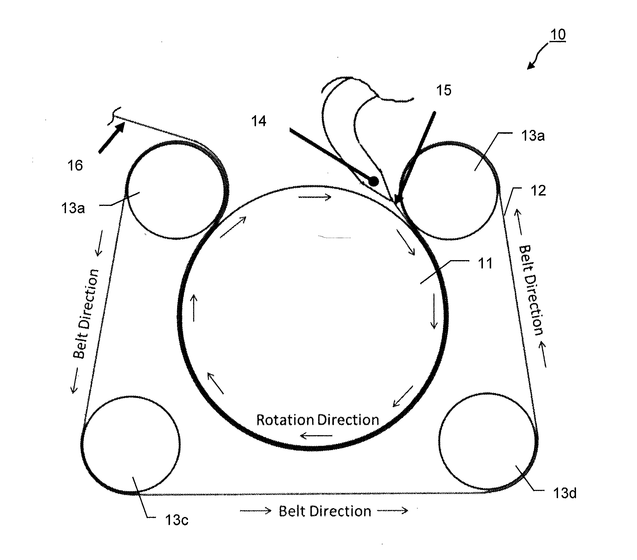
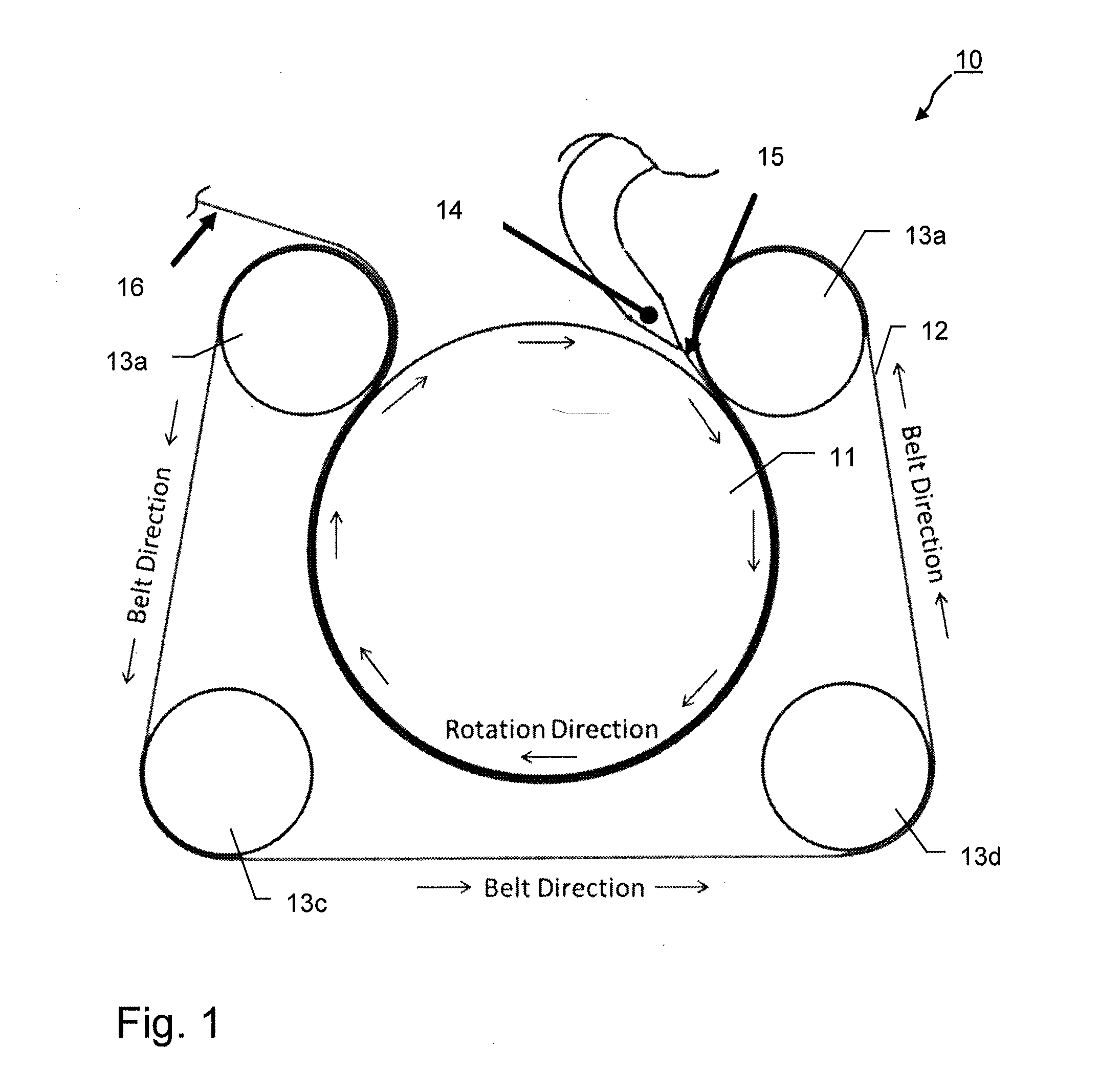
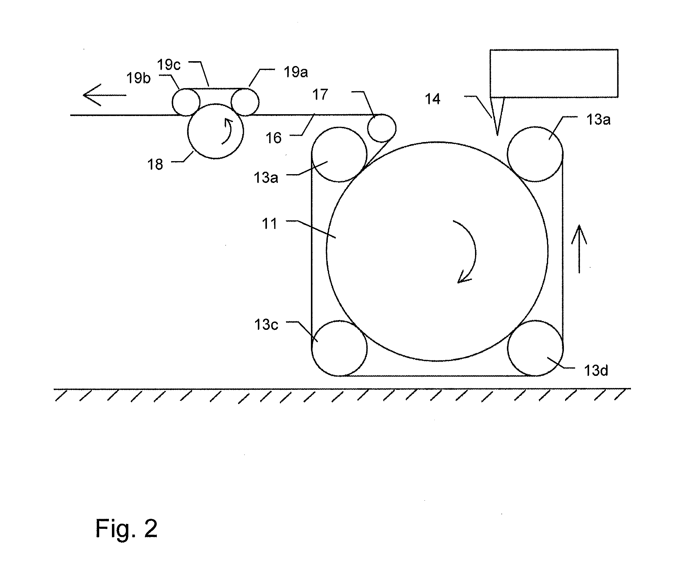
[0034]An embodiment of a continuous molding apparatus 10 is shown schematically in FIG. 1. The apparatus has a mold wheel 11 and a moving belt 12 tensioned around the mold wheel 11 by means of four guide rollers 13a-d. The belt 12 has the form of a closed loop and runs from guide roller 13a around the mold wheel 11 to guide roller 13b, where it leaves the mold wheel and is guided in reverse direction via guide rollers 13c and 13d back to guide roller 13a. Between guide rollers 13a and 13b, the belts engages firmly against the outer surface of the mold wheel 11 and moves in the same direction and with the same speed as mold wheel 11 rotates.

[0035]Mold wheel 11 is driven to rotate by a motor (not shown). Moving belt 12 tensioned around mold wheel 11 can be moved passively with the mold wheel 11 through friction between its inner belt surface and the outer surface of the mold wheel 11, or can be driven separately by the same or an additional motor (not shown). In the latter case, the i...


PUM

PropertyMeasurementUnit
Temperatureaaaaaaaaaa
Forceaaaaaaaaaa

Abstract

A method and related apparatus for manufacturing a continuous strip member having at least one surface structured with a surface pattern are described, which employs a rotating mold wheel in conjunction with a belt tensioned around and moving with the rotating mold wheel. A continuous bead of molten thermoplastic material is drawn and applied between the rotating mold wheel and the moving belt to extrude the continuous strip member. The mold wheel carries on its outer circumference a structure serving as a series of mold cavities designed to form the surface pattern onto the continuous strip member. The moving belt applies a compressive force onto the molten thermoplastic material thus forcing the material into the mold cavities until the material has sufficiently solidified, thereby taking on the contours of the mold cavities.

Description

INCORPORATION BY REFERENCE[0001]The following documents are incorporated herein by reference as if fully set forth: European Patent Application No. 14 185 075.0, filed Sep. 17, 2014.FIELD OF THE INVENTION[0002]The present invention relates to the field of micro-irrigation and more particularly to a method and related apparatus for manufacturing of a continuous molded irrigation emitter strip for use in a drip irrigation hose.BACKGROUND OF THE INVENTION[0003]In modern agriculture today, with the ever growing human population and the dwindling water resources, particularly in arid regions of the world, micro-irrigation systems have gained increasing importance over older irrigation methods, such as flood irrigation and sprinkler systems.[0004]Micro-irrigation, also often termed drip irrigation, is an irrigation method that in proper application, delivers water in small doses directly to the roots of plants, either onto the soil surface or directly onto the root zone of crop plants. Th...

Claims


Application Information

Patent Timeline
IPC IPC(8): B29C43/24B29C48/08B29C48/35
CPCB29C47/0061B29C47/0021B29L2031/7004B29K2023/06B29C43/24A01G25/023B29C43/222B29C2043/463B29C2043/486B29C48/002B29C48/08
Inventor VERELIS, CHRISTOSPARASKEVOPOULOS, DIMITRIS
Owner ADVANCED AUTOMATION SYST
Why Eureka
Try Eureka