
Ideal diode

a diode and diode technology, applied in the direction of d transporting and packaging, ac network circuit arrangement, etc., can solve the problem of not being desirable in micro solar charging system

Active Publication Date: 2016-03-17
ATOM H2O LLC
View PDF6 Cites 7 Cited by
  • Summary
  • Abstract
  • Description
  • Claims
  • Application Information

AI Technical Summary

Benefits of technology

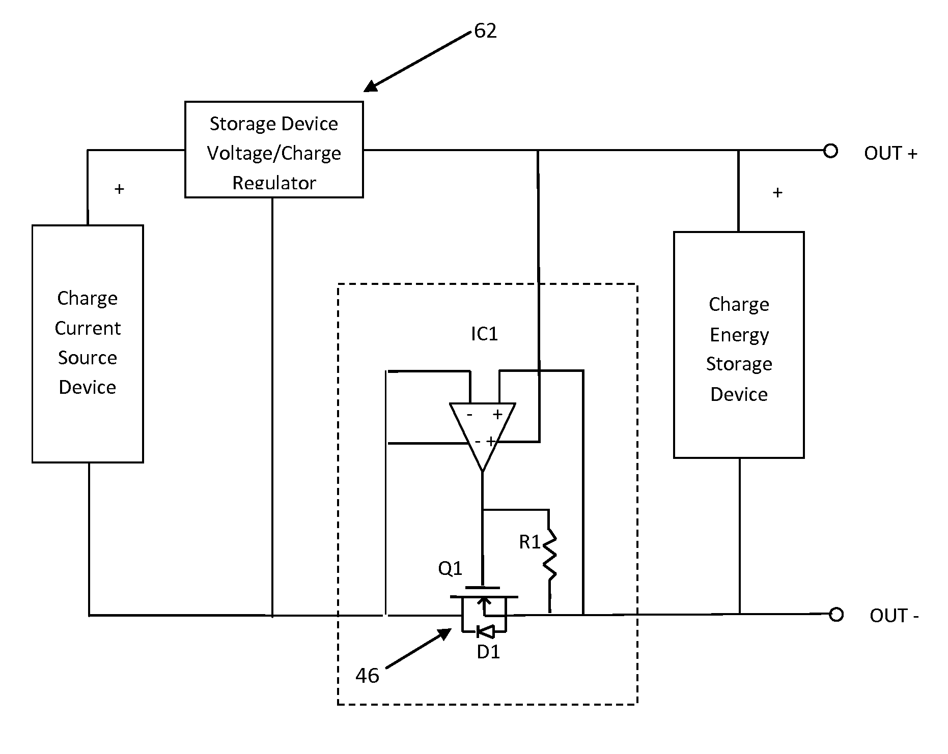
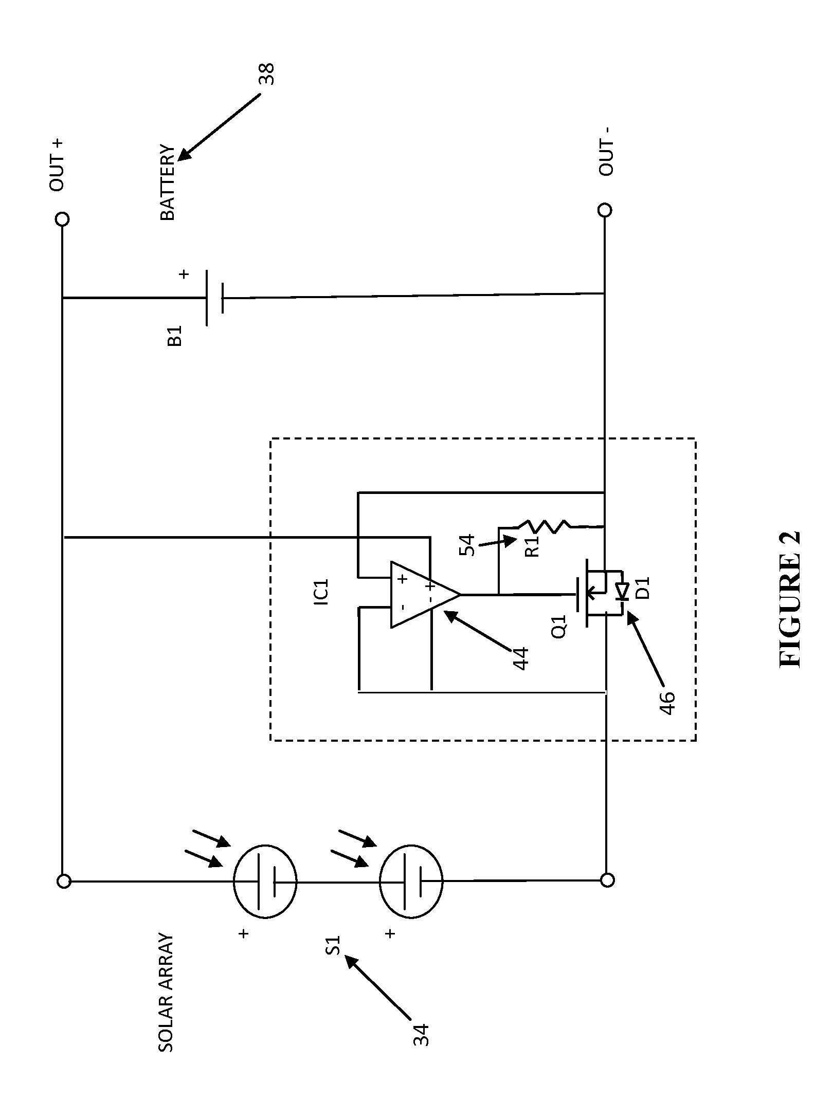
The patent describes an ideal diode for energy harvesting systems that combines a field effect transistor and an operational amplifier. The transistor is operated by the amplifier and has a pull down resistor to connect and disconnect the power source to the device. The ideal diode allows for minimal reverse back current flow when the power source is disconnected. The operational amplifier is powered by the power source, and the pull down resistor ensures that the ideal diode switches off when no power source is available. In simple terms, this patent describes a device that helps manage power sources for energy harvesting systems.

Problems solved by technology

However, this is not desirable in micro solar charging systems where the charge voltages are not high in ratio to the Schottky diode forward voltage drop.

Method used


Image

  • Ideal diode
  • Ideal diode
  • Ideal diode

Examples


Embodiment Construction

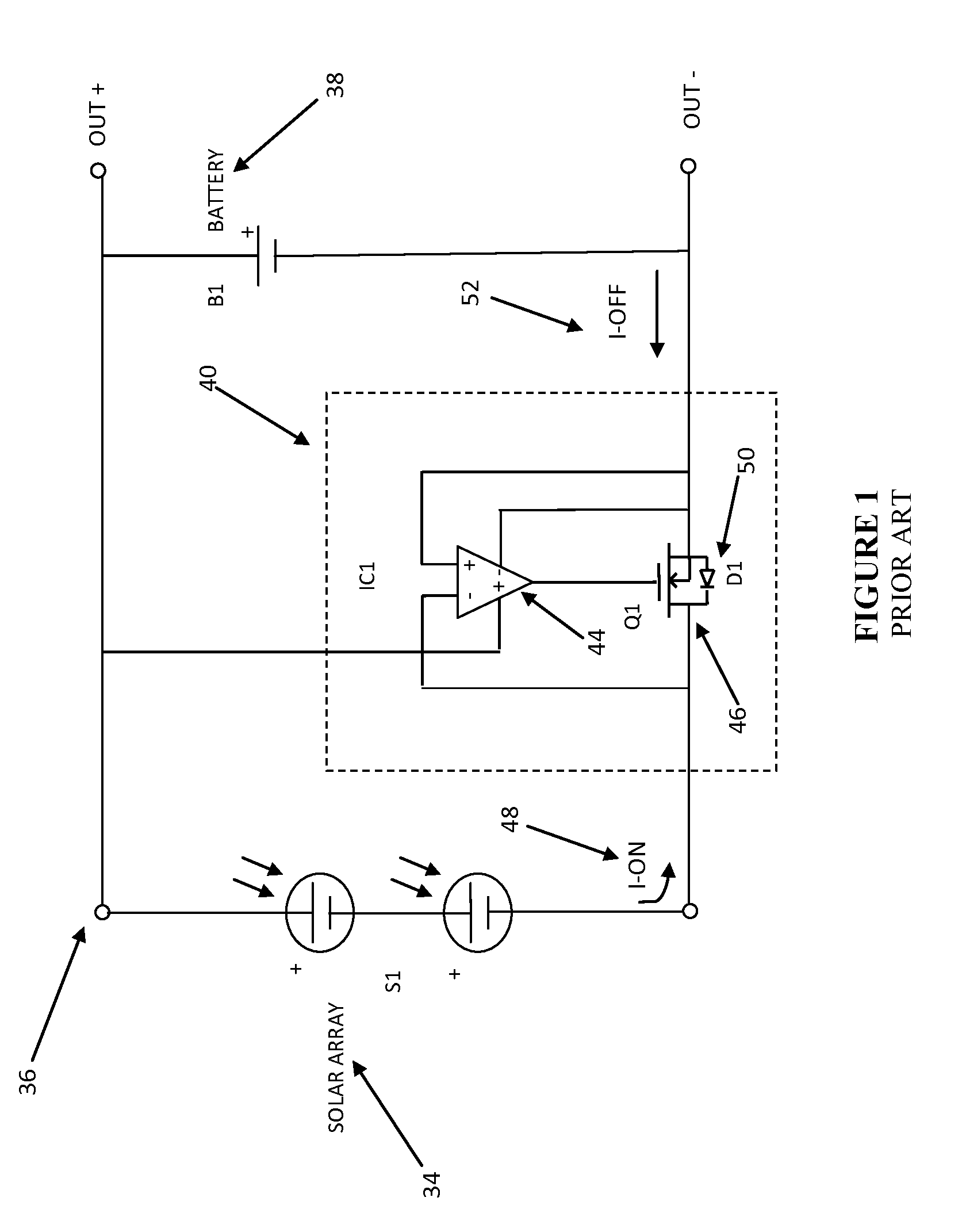
[0011]Referring to FIG. 1 there is shown a prior art circuit diagram 36 of an intermittent current limited power source such as a solar array S1 34 connected to a device for storing charge such as a battery B1 38 through an active switch circuit 40. The active switch circuit 40 substantially reduces the power that is lost by conventional reverse current diodes normally associated with solar charging devices. Referring once again to FIG. 1, the active switch circuit 40 consists of a reverse current detector IC1 44 and a low loss N-channel enhancement mode MOSFET switch Q1 46 having an internal diode D150. In operation, incident solar energy generated by solar array S1 34 causes a counter clockwise current flow to occur as shown by “I-on”48 in FIG. 1. The solar array 34 electromotive force (EMF) forward biases D150 and current begins to flow. The reverse current detector IC1 44, which in this embodiment is shown as a differential amplifier detects the positive difference voltage acros...


PUM


Abstract

An active switch for electrically connecting and disconnecting a power source such as an energy harvester to a charge storage device is disclosed. The active switch allows a minimal amount of reverse back current flow from the charge storage device to the power source and zero quiescent current from the charge storage device to the active switch having a high off-resistance.

Description

BACKGROUND[0001]Conventional solar battery charging systems employ a “back flow” or reverse current diode to prevent battery current from flowing back through a solar array in the absence of solar energy. Typically, a Schottky diode is used for this reverse current protection due to a low forward voltage drop inherent for Schottky diode operation. The forward voltage drop has a direct impact on charge efficiency such that the less power that is dissipated across the diode, the more charge power is delivered to the battery. The charge efficiency has been acceptable when dealing with macro solar charging systems since the battery charge voltages have been typically “high” in ratio to the Schottky diode forward voltage drop. However, this is not desirable in micro solar charging systems where the charge voltages are not high in ratio to the Schottky diode forward voltage drop. Therefore it would be desirable to provide a circuit that prevents battery back flow current having less forwa...

Claims


Application Information

Patent Timeline
Patent Type & Authority Applications(United States)
IPC IPC(8): H02J7/35H02J1/00
CPCH02J1/00H02J7/35H02J7/32H02J50/001
Inventor REYNOLDS, ROBERT
Owner ATOM H2O LLC
Learn More