Medical treatment system and methods using a plurality of fluid lines

Active Publication Date: 2016-03-24
DEKA PROD LLP
View PDF2 Cites 46 Cited by
  • Summary
  • Abstract
  • Description
  • Claims
  • Application Information

AI Technical Summary

Benefits of technology

[0070]In another embodiment, the system may include an interface (such as a visual display with a touch screen component) that is movably mounted to the housing and is movable between a first position in which the interface is received in the heater bag receiving section, and a second position in which the interface is located out of the heater bag receiving section (e.g., a position in which a user may interact with the interface). Thus, the interface may be hidden from view when the system is idle, allowing the interface to be protected. Also, storing the interface in the heater bag receiving section may make the system more compact, at least in an “as stored” condition.
[0071]In another aspect of the invention, a dialysis system includes a supply of pneumatic pressure and/or vacuum suitable for controlling pneumatically-operated components of the system, a pneumatically-operated component that is fluidly connected to the supply of pneumatic pressure and/or vacuum, and a control system that provides pneumatic pressure or vacuum to the pneumatically-operated component and subsequently isolates the pneumatically-operated component from the supply of pneumatic pressure or vacuum for a substantial period of time before again providing pneumatic pressure or vacuum to the pneumatically-operated component. Such an arrangement may be useful for components that are actuated relatively infrequently, such as the occluder arrangement described herein. Small motions of some components may cause the component to emit noise that may be found bothersome by a patient. By isolating the component from the pneumatic pressure/vacuum, the component may avoid slight movement caused by variations in the supply pressure/vacuum, e.g., resulting from draws on the pressure/vacuum by other system components. In one embodiment, the substantial period of time may be 5 minutes or more, 1 hour or more, 50% or more of a time period required to deliver or remove a volume of dialysate suitable for a dialysis treatment with respect to a patient's peritoneal cavity, or other suitable periods.
[0072]In another aspect of the invention, a dialysis system includes a supply of pneum

Problems solved by technology

IPD can also be used when a patient requires PD, but cannot undertake the responsibilities of CAPD or otherwise do it at home.
Still, the complexity and size of past ma

Method used


Image

  • Medical treatment system and methods using a plurality of fluid lines
  • Medical treatment system and methods using a plurality of fluid lines
  • Medical treatment system and methods using a plurality of fluid lines

Examples


Embodiment Construction

[0216]Although aspects of the invention are described in relation to a peritoneal dialysis system, certain aspects of the invention can be used in other medical applications, including infusion systems such as intravenous infusion systems or extracorporeal blood flow systems, and irrigation and / or fluid exchange systems for the stomach, intestinal tract, urinary bladder, pleural space or other body or organ cavity. Thus, aspects of the invention are not limited to use in peritoneal dialysis in particular, or dialysis in general.

[0217]APD System

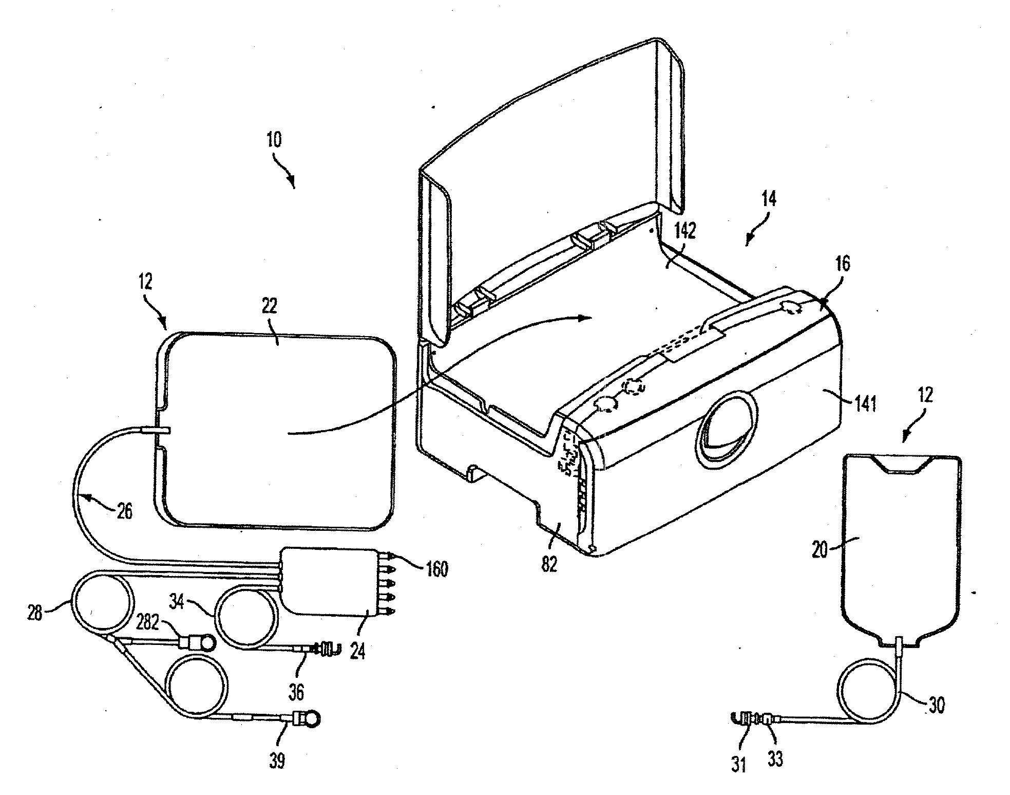
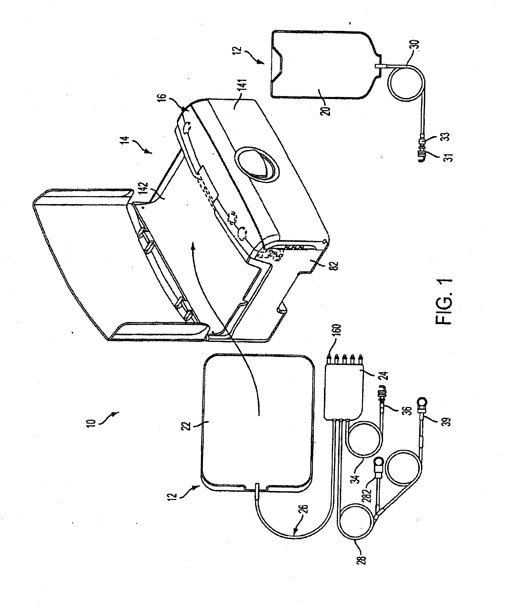
[0218]FIG. 1 shows an automated peritoneal dialysis (APD) system 10 that may incorporate one or more aspects of the invention. As shown in FIG. 1, for example, the system 10 in this illustrative embodiment includes a dialysate delivery set 12 (which, in certain embodiments, can be a disposable set), a cycler 14 that interacts with the delivery set 12 to pump liquid provided by a solution container 20 (e.g., a bag), and a control system 16 (e.g...


PUM


Abstract

A medical treatment system, such as peritoneal dialysis system, may include control and other features to enhance patient comfort and ease of use. For example, a peritoneal dialysis system may include a control system that can adjust the volume of fluid infused into the peritoneal cavity to prevent the intraperitoneal fluid volume from exceeding a pre-determined amount. The control system can adjust by adding one or more therapy cycles, allowing for fill volumes during each cycle to be reduced. The control system may continue to allow the fluid to drain from the peritoneal cavity as completely as possible before starting the next therapy cycle. The control system may also adjust the dwell time of fluid within the peritoneal cavity during therapy cycles in order to complete a therapy within a scheduled time period. The cycler may also be configured to have a heater control system that monitors both the temperature of a heating tray and the temperature of a bag of dialysis fluid in order to bring the temperature of the dialysis fluid rapidly to a specified temperature, with minimal temperature overshoot.

Description

[0001]This application is a division of U.S. patent application Ser. No. 13 / 667,696, filed Nov. 2, 2012 and issued as U.S. Pat. No. 9,078,971 on Jul. 14, 2015, which is a continuation in part of U.S. application Ser. No. 13 / 178,191, filed Jul. 7, 2011 and issued as U.S. Pat. No. 8,708,950 on Apr. 29, 2014, which claims the benefit of and U.S. Provisional application No. 61 / 362,259, filed Jul. 7, 2010.[0002]This application is a continuation in part of U.S. application Ser. No. 12 / 864,357, filed Jul. 23, 2010, which was the National Stage of International Application No. PCT / US2009 / 000440, filed Jan. 23, 2009, which claims the benefit of U.S. Provisional application No. 61 / 011,967, filed Jan. 23, 2008 and U.S. Provisional application No. 61 / 058,469, filed Jun. 3, 2008.[0003]This application is a continuation in part of U.S. application Ser. No. 12 / 864,378, filed Jul. 23, 2010, which was the National Stage of International Application No. PCT / US2009 / 000436, filed Jan. 23, 2009, which ...

Claims


Application Information

Patent Timeline
IPC IPC(8): A61M1/28A61M5/44
CPCA61M1/28A61M1/288A61M2205/3306A61M2205/3673A61M2205/3368A61M5/44A61M2205/14A61M2205/3331A61M2205/12A61M2205/3389A61M2205/502A61M2205/6072A61M1/166A61M1/282A61M2205/8206A61M1/153A61M1/155A61M1/1565A61M1/159A61M1/1524A61M1/1522A61M1/1561A61M1/1629A61M1/1664A61M2205/50A61M2205/127A61M2205/36
Inventor COLL, ANDREW, S.KERWIN, JOHN, M.SCARPACI, JACOB, W.
Owner DEKA PROD LLP
Why Eureka
Try Eureka