Hifu treatment optimization in vicinity of sensitive zones

a sensitive zone and ultrasonic treatment technology, applied in the field of high intensity focused ultrasonic treatments, can solve the problem of practicably impossible to determine optimal exposure limits, and achieve the effects of minimizing the exposure of at least one sensitive zone, minimizing the exposure of sonication, and efficient monitoring

Inactive Publication Date: 2016-03-24
KONINKLJIJKE PHILIPS NV
View PDF11 Cites 7 Cited by
  • Summary
  • Abstract
  • Description
  • Claims
  • Application Information

AI Technical Summary

Benefits of technology

[0024]According to a preferred embodiment the control unit is adapted to receive temperature information of at least a part of the area covered by ultrasonic irradiation device, and the control unit is adapted to individually control the transducer elements by comparing the temperature information to the pre-defined heating requirements. The corresponding method comprises the additional step of providing temperature information of at least a part of the area covered by the ultrasonic irradiation device, and wherein the step of individually controlling the transducer elements in phase and amplitude, so that the pre-defined heating requirements are met and the exposure of at least one sensitive zone is minimized, comprises individually controlling the transducer elements by comparing the temperature information to the pre-defined heating requirements. With the knowledge of the temperature information, the heating of the target zone as well as the exposure of the sensitive zone can be determined to adapt the control of the ultrasonic irradiation device. In particular, the heating of sensitive zones is difficult to predict, so that they can be efficiently monitored to minimize their exposure to the sonications. Preferably, the temperature information is obtained by performing a magnetic resonance scan. The control unit may comprise an electronic interface for receiving the temperature information in any suitable format.
[0025]According to a preferred embodiment the ultrasonic irradiation device comprises a deflection unit, and the control unit is adapted to perform a control of the deflection unit and / or the transducer elements to deflect the sonications of ultrasonic energy from the ultrasonic irradiation device to the target zone to minimize the heating of the at least one sensitive zone. In the corresponding method, the step of individually controlling the transducer elements in phase and amplitude, so that the pre-defined heating requirements are met and the exposure of at least one sensitive zone is minimized, comprises deflecting the sonications of ultrasonic energy from the ultrasonic irradiation device to the target zone to minimize the heating of the at least one sensitive zone. Accordingly, the ultrasonic irradiation can at least partially be directed to the target zone without passing through the sensitive zone. Without deflection, there can be a large overlap between the beam of the ultrasonic irradiation and the sensitive zone. By using deflection, the overlap can be reduced while still targeting the same focal point.
[0026]According to a preferred embodiment the deflection unit is an electronic deflection unit for electronically deflecting the sonications. In the corresponding method, the step of deflecting the sonications of ultrasonic energy from the ultrasonic irradiation device to the target zone comprises electronically deflecting the sonications. This can be easily applied to perform the deflection of the sonications. Preferably, electronic deflection is chosen based on the criteria that acoustic exposure on the sensitive zone is not exceeded.
[0027]According to a preferred embodiment the control unit is adapted to control the transducer elements to perform volumetric sonications. In the corresponding method, the step of individually controlling the transducer elements in phase and amplitude, so that the pre-defined heating requirements are met and the exposure of at least one sensitive zone is minimized, comprises controlling the transducer elements to perform volumetric sonications. In single-point sonication, the focal point of the ultrasonic irradiation is kept at fixed position, and the thermal dose is controlled through the applied power and the duration of the sonication. Volumetric sonications comprise of a series of rapidly interleaved single-point sonications, which on the time scale of thermal diffusion appear as simultaneous. Therefore, when performing volumetric sonication, the focal point is moved along a planned trajectory, distributing the heating across the desired volume. Preferably, this is achieved by a combination of using tranducers having phased arrays of transducer elements and electric deflection. The volumetric sonications are chosen based on the criteria that acoustic exposure on the sensitive zones is not exceeded. This maximizes the treatable volume without endangering the sensitive zone. This can be applied either in near-field, to protect scars or other sensitive tissues, or in far-field, to protect the spine and / or bowels. An advantage of volumetric sonications is that they are more energy-effective than single-point sonications, so that more volume can be treated for the same amount of energy.
[0028]According to a preferred embodiment the control unit is adapted to select volumetric cells from a list of predefined volumetric cells, and the control unit is further adapted to locate the volumetric cells within the target zone. In the corresponding method, the step of controlling the transducer elements to perform volumetric sonications comprises forming volumetric cells within the target zone based on the shape of the target zone and / or the shape and position of the at least one sensitive zone, and locating the volumetric cells within the target zone. The predefined cells can have any shape, e.g. spherical, ellipsoid, cubical or others. Hence, the volumetric cells can be easily applied for each treatment enable treatments with a low preparation time. The control unit can automatically select the volumetric cells and locate them within the target zone, or it can be adapted to receive a selection of the volumetric cells and their locations. The control unit can also have a user interface for interacting with a user to select and locate the volumetric cells.
[0029]According to a preferred embodiment the control unit is adapted to form volumetric cells within the target zone based on the shape of the target zone and / or the shape and the position of the at least one sensitive zone, and the control unit is further adapted to locate the volumetric cells within the target zone. In the corresponding method, the step of controlling the transducer elements to perform volumetric sonications comprises forming volumetric cells on the target zone and / or the information on the at least one sensitive zone, and locating the volumetric cells within the target zone. Hence, the volumetric cells can be adapted to each treatment individually to achieve the best heating of the target zone. The control unit can automatically form the volumetric cells and locate them within the target zone, or it can be adapted to receive a definition of the volumetric cells and their locations. The control unit can also have a user interface for interacting with a user to define and locate the volumetric cells.

Problems solved by technology

For example, when scars define a sensitive zone, it is practically impossible to determine optimal exposure limits.
Hence, often the state of the art methods deny sonications, which would be actually feasible.

Method used


Image

  • Hifu treatment optimization in vicinity of sensitive zones
  • Hifu treatment optimization in vicinity of sensitive zones

Examples


Embodiment Construction

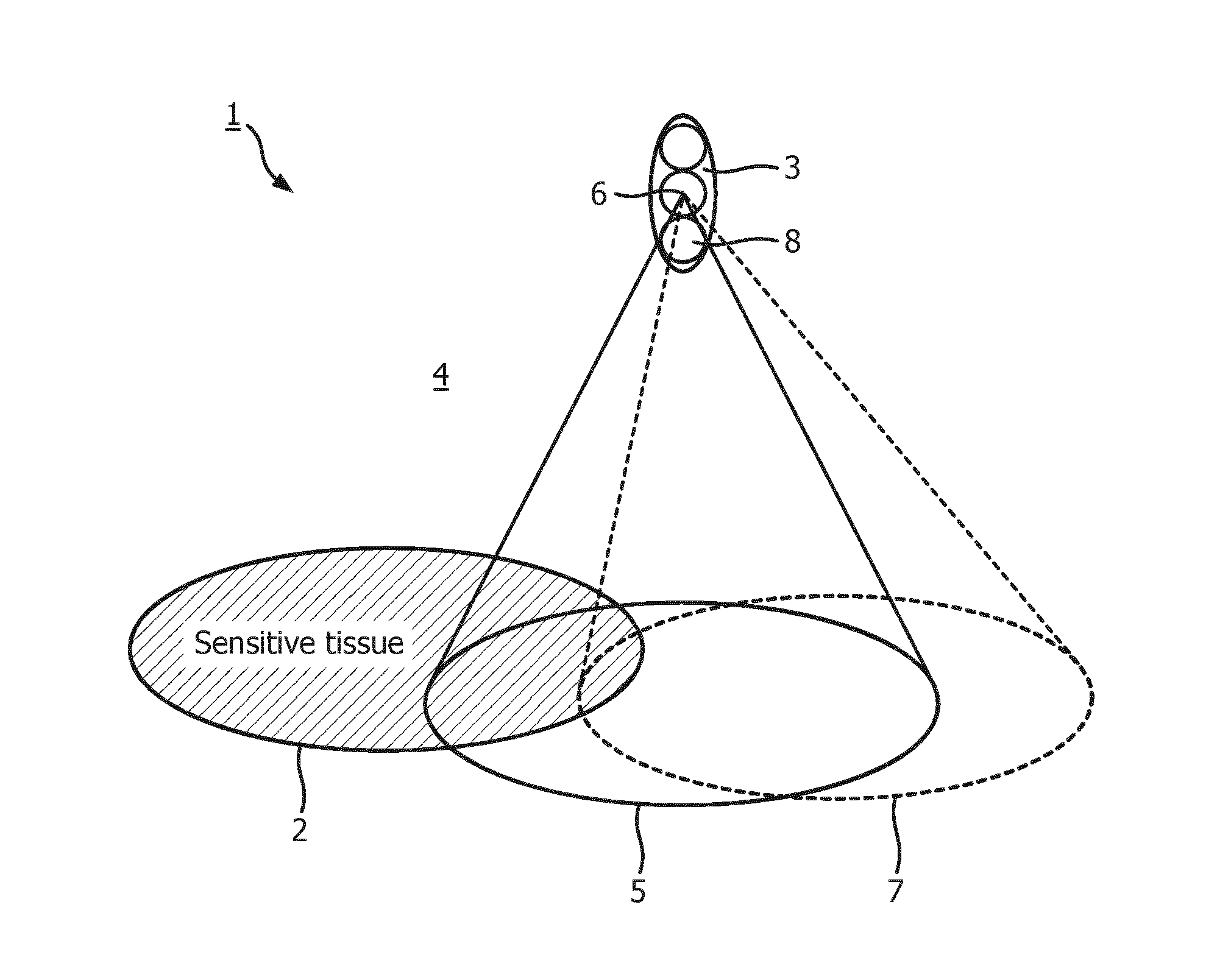
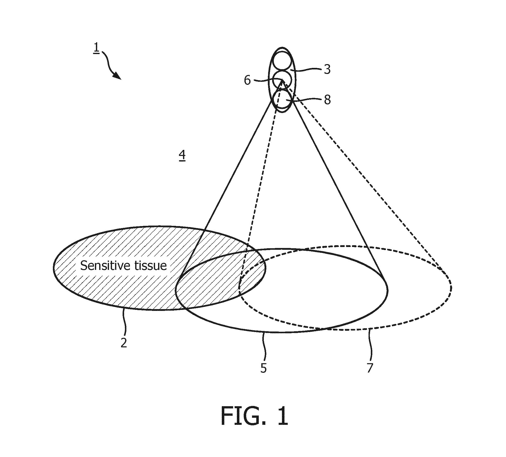
[0033]FIG. 1 shows a schematic illustration of a subject of interest 1 having a sensitive zone 2, which is a scar in this embodiment. Furthermore, a zone of cancerous tissue can be seen in the FIG., which corresponds to a target zone 3 for treatment with an ultrasonic irradiation device, which is HIFU device in this embodiment. The HIFU device is not shown in the FIG. The target zone 3 is heated according to pre-defined heating requirements using ultrasonic irradiation from the HIFU device. The pre-defined heating requirements in this embodiment refer to a thermal dose to be applied to the target zone 3 to ablate the tissue within the target zone 3.

[0034]The sensitive zone 2 is defined within an area 4 covered by ultrasonic irradiation device based on a diagnostic image, which is in this embodiment a 3-dimensional MR scan provided using a magnetic resonance imaging device. The diagnostic image covers the area 4 covered by ultrasonic irradiation device, which includes the target zone...


PUM


Abstract

The present invention provides a method for heating a target zone (3) of a subject of interest (1) according to pre-defined heating requirements using ultrasonic irradiation, comprising the steps of providing an ultrasonic irradiation device comprising a set of individually controllable transducer elements in vicinity of the target zone (3), defining at least one sensitive zone (2) within an area (4) covered by ultrasonic irradiation device, and controlling the ultrasonic irradiation device to apply sonications of ultrasonic energy to the target zone (3) to achieve the desired heating thereof, wherein the transducer elements are individually controlled in phase and amplitude to provide the sonications as a beam (5) directed towards the target zone (3), wherein the beam (5) has a energy distribution so that the pre-defined heating requirements of the target zone (3) are met and the exposure of the at least one sensitive zone (2) is minimized The present invention further provides an ultrasonic irradiation device adapted to perform the above method. By individually controlling the transducer elements, beam shaping of the ultrasonic irradiation can be applied over sensitive zones like scars, bones, bowels, spines or others without associating an intensity limit or energy exposure limit thereto. Such a configuration of active elements is sought, that the exposure on the sensitive zone is minimized, without compromising focal properties or violating restrictions on the number of active elements.

Description

FIELD OF THE INVENTION[0001]The invention relates to the field of High Intensity Focused Ultrasonic Treatments of a subject of interest.BACKGROUND OF THE INVENTION[0002]Focused ultrasound systems are used for delivering sonications of acoustic energy into a tissue region within a patient to coagulate or otherwise treat the tissue region with thermal energy. Typical applications of ultrasonic heating are the treatment of cancerous or benign tumors, which are located in the treated tissue region, also referred to as target zone. For example, a piezoelectric transducer located outside the patient's body may be used to focus high intensity acoustic waves, such as ultrasonic waves (acoustic waves with a frequency greater than about twenty kilohertz (20 kHz)), in an internal tissue region of the patient to treat the internal tissue region. The acoustic waves may be used to ablate a tumor, thereby eliminating the need for invasive surgery. Such focused ultrasound systems are in particular ...

Claims


Application Information

Patent Timeline
Patent Type & Authority Applications(United States)
IPC IPC(8): A61N7/02
CPCA61N7/02A61B2017/00084A61N2007/0086A61B2090/0472A61B2034/101A61B2090/374
Inventor KOSKELA, ILPO, ASKO, JULIUSNURMILAUKAS, KIRSI, ILONATOLO, JAAKKO, JUHANIVUORINEN, REKO, TAPIO
Owner KONINKLJIJKE PHILIPS NV
Why Eureka
Try Eureka