Shield and electron beam container sterilization equipment

Active Publication Date: 2016-03-24
HITACHI ZOSEN CORP
View PDF11 Cites 8 Cited by
  • Summary
  • Abstract
  • Description
  • Claims
  • Application Information

AI Technical Summary

Benefits of technology

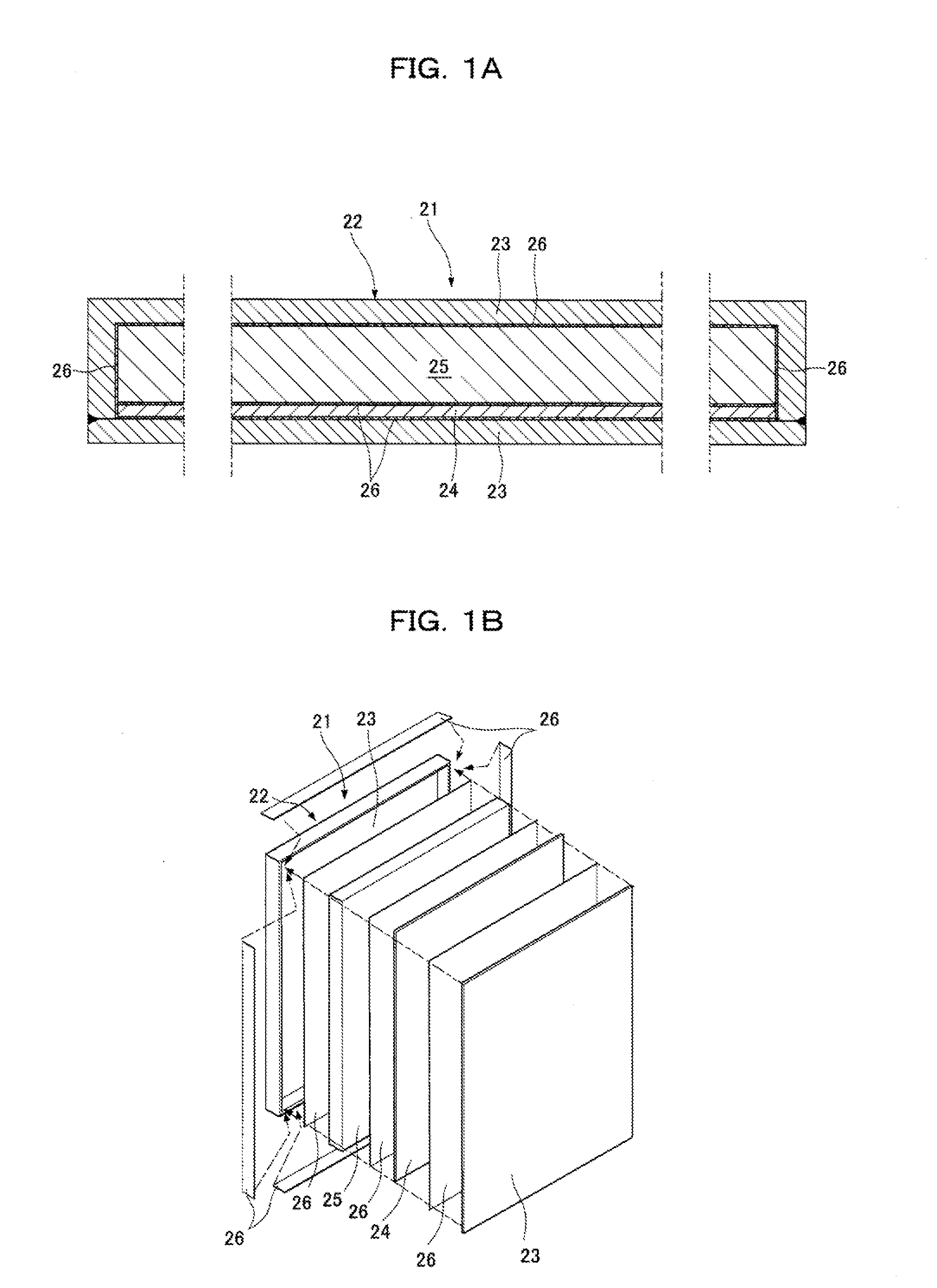
[0021]According to the invention of the first aspect, the magnetic shield layer and the X-ray shield layer are disposed between the corrosion resistant layers so as to form a shield layer. Thus, the X-ray shield layer can block and effectively attenuate X-rays. Moreover, the magnetic shield layer can prevent geomagnetism from curving electron beams, allowing the electron beams to stably sterilize the container. Furthermore, the corrosion resistant layers can prevent corrosion in an atmosphere of hydrogen peroxide or ozone, and the insulating layer can prevent galvanic corrosion caused by a potential difference between dissimilar metals.
[0022]In this case, “layers” of the shield layer and the corrosion resistant layer include a layer bonded by application, spraying, or vapor deposition on a molded or cut plate or member, and include a shield composed of a magnetic shield layer, an insulating layer, and a corrosion resistant layer with one of the shield layers, for example, the X-ray shield layer serving as a base material.
[0023]According to the invention of the second aspect, the magnetic shield and the X-ray shield of the composite shield block are disposed in the hollow section of the board-shaped shell made of a corrosion resistant material. Furthermore, the insulating layer is interposed among the corrosion resistant layer, the magnetic shield, and the X-ray shield. Thus, X-rays can be blocked and effectively attenuated by the X-ray shield and the magnetic shield c

Problems solved by technology

An electron dose is kept at a predetermined value or less because an excessive electron dose may cause alteration, coloring, or odor on the container.
In the technique for sterilizing the inner surface with the irradiation nozzle, electron beams emitted from the exit window of the irradiation nozzle are spread but a suppressed electron dose limits a sterilization range, requiring the exit window to move close to the bottom of a container.
The effect of geomagnetism on the above irradiation nozzle may curve ele

Method used


Image

  • Shield and electron beam container sterilization equipment
  • Shield and electron beam container sterilization equipment
  • Shield and electron beam container sterilization equipment

Examples


Example

[0033]Referring to FIGS. 1 to 4, a first embodiment of container sterilization equipment according to the present invention will be described below.

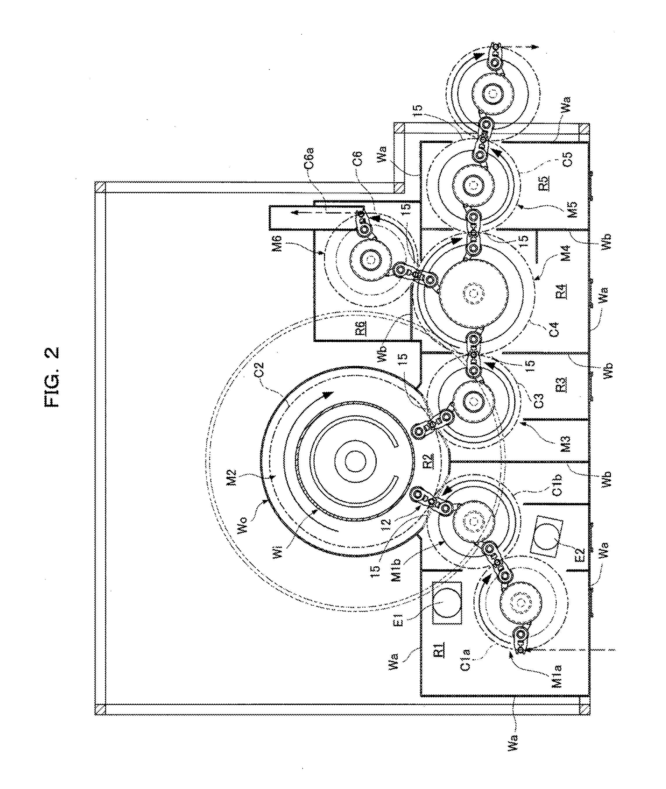
[0034]As shown in FIGS. 2 to 4, the container sterilization equipment includes, from the inlet to the outlet of containers B, an outer sterilizing chamber R1, an inner sterilizing chamber R2, a first delivery chamber R3, a second delivery chamber R4, a trap chamber R5, and a reject chamber R6. The chambers R1 to R6 contain rotary conveyors M1a and M1b to M6, respectively, that transport the containers B along circular paths C1a and C1b to C6 around vertical axes. The circular paths C1a and C1b to C5 are connected in series. The circular path C6 of the reject chamber R6 is branched and connected to the circular path C4 of the second delivery chamber R4. If the container B is insufficiently sterilized and is transported to the circular path C6, the container B is discharged from a delivery path C6a.

[0035]In the outer sterilizing chamber R...

Example

Second Embodiment

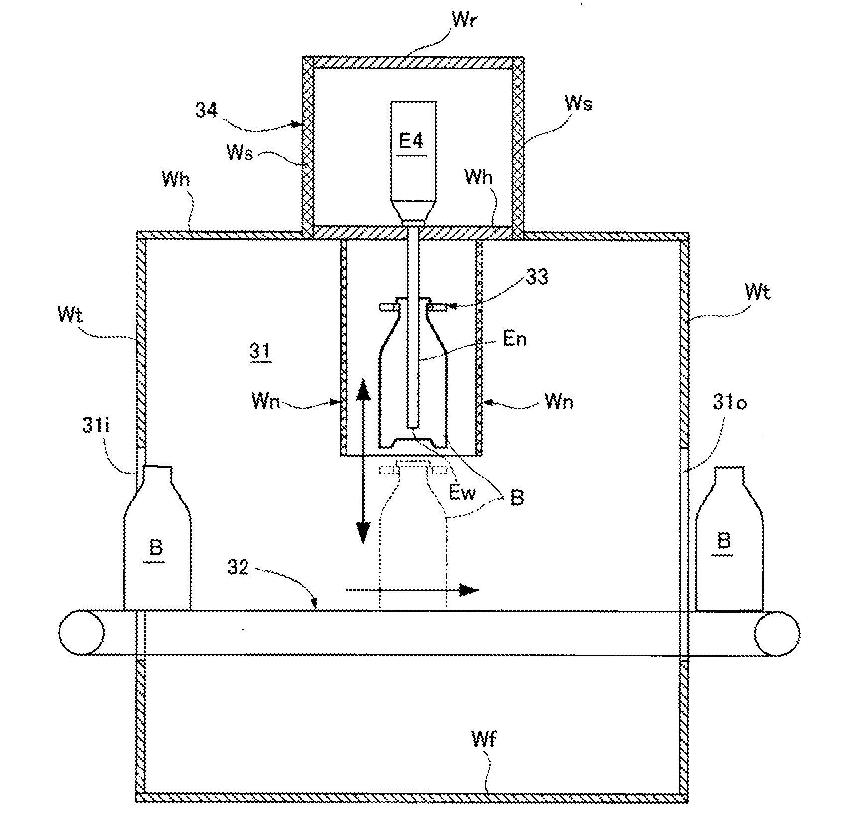
[0051]FIGS. 5 and 6 show a second embodiment of electron beam sterilization equipment according to the present invention. FIGS. 5 and 6 are schematic plan and side cross-sectional views of an inner sterilizing part. The same members as those of the first embodiment are indicated by the same reference numerals and the explanation thereof is omitted.

[0052]A belt conveyor 32, an example of a container conveyor, is installed in an inner sterilizing chamber 31 surrounded by a side wall shield Wt, a bottom wall shield Wf, and a ceiling wall shield Wh, the belt conveyor 32 extending along a container transport path Cs from a container inlet 31i to a container outlet 310 of the inner sterilizing chamber 31. The belt conveyor 32 transports containers B that are intermittently moved at regular intervals. The inner sterilizing chamber 31 corresponding to a container stop position on the belt conveyor 32 is provided with a container elevating device (not shown) that holds the n...


PUM


Abstract

Provided is a shield used for container sterilization equipment that inserts, from the mouth of a container (B), an irradiation nozzle (En) having an exit window (Ew) on the distal end of the irradiation nozzle (En) and sterilizes the inner surface of the container (B), the irradiation nozzle (En) being surrounded by composite shields (Wi, Wo). A composite shield block (21) forming the composite shields (Wi, Wo) includes a magnetic shield (24) and an X-ray shield (25) that are disposed in the hollow section of a board-shaped shell (22) made of a corrosion resistant material, and an insulating layer (26) that is interposed between one surface of the board-shaped shell (22) and the magnetic shield (24), between the magnetic shield (24) and the X-ray shield (25), and between the X-ray shield (25) and one surface of the board-shaped shell (22).

Description

TECHNICAL FIELD[0001]The present invention relates to a shield used for an electron beam sterilizer and electron beam container sterilization equipment.BACKGROUND ART[0002]Electron beams (cathode rays) emitted for sterilizing cellular microorganisms collide with metallic components constituting a sterilizer, for example, a stainless holder for holding a container, and thus the electron beams are attenuated and generate braking X-rays or characteristic X-rays. The X-rays are spread widely and then are reflected and diffracted. For example, X-rays having been collided with a shield three to four times can be attenuated to intensity that does not affect a human body, depending on the intensity of X-rays.[0003]It is known that the direction of an electron beam is curved by the effect of a magnetic field. When the outer surface of a container is sterilized by electron beam irradiation, electron beams are widely emitted to the container from an electron beam generator through a wide exit ...

Claims


Application Information

Patent Timeline
IPC IPC(8): B65B55/08A61L2/08A61L2/26
CPCB65B55/08A61L2/087A61L2/26G21K5/04
Inventor YOKOBAYASHI, TAKAYASUSAKAI, ICHIRO
Owner HITACHI ZOSEN CORP
Why Eureka
Try Eureka