Optical sheet member and image display device using same

Active Publication Date: 2016-03-24
FUJIFILM CORP
View PDF6 Cites 25 Cited by
  • Summary
  • Abstract
  • Description
  • Claims
  • Application Information

AI Technical Summary

Benefits of technology

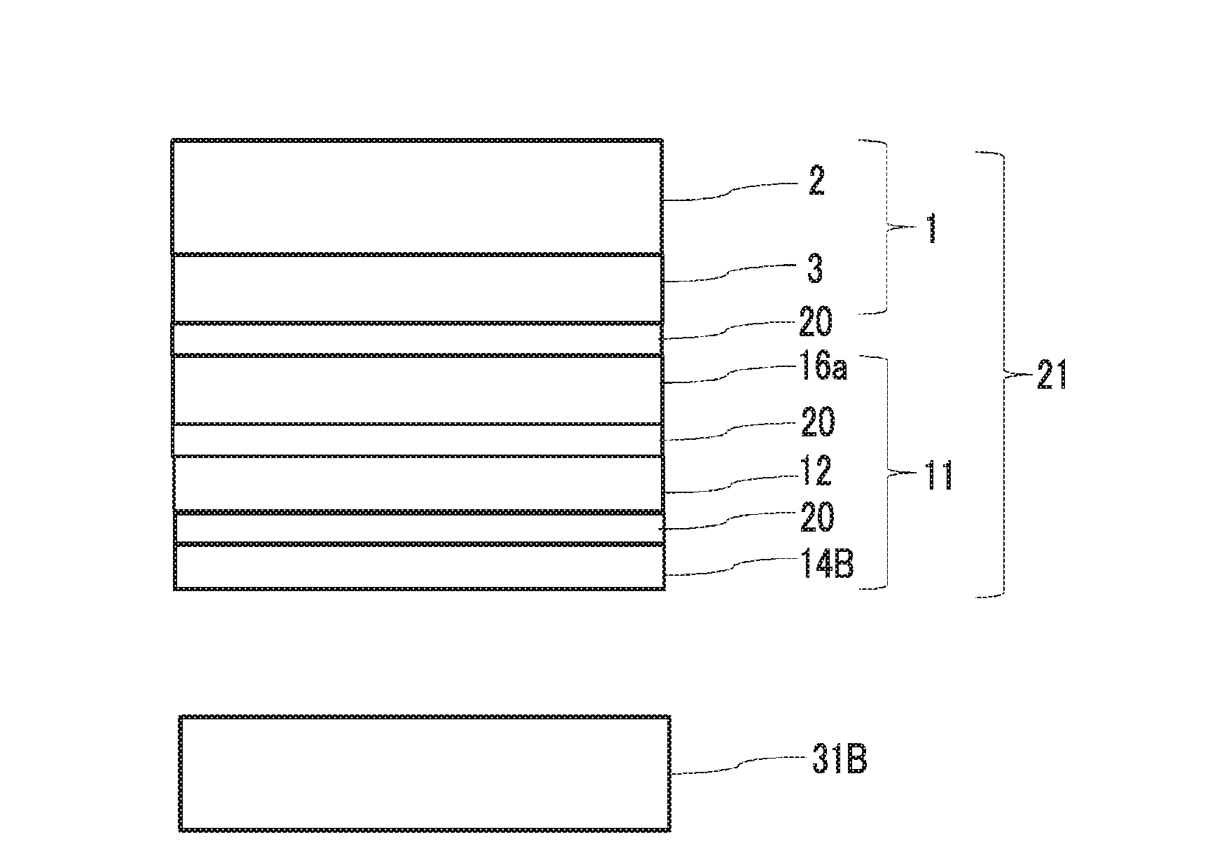
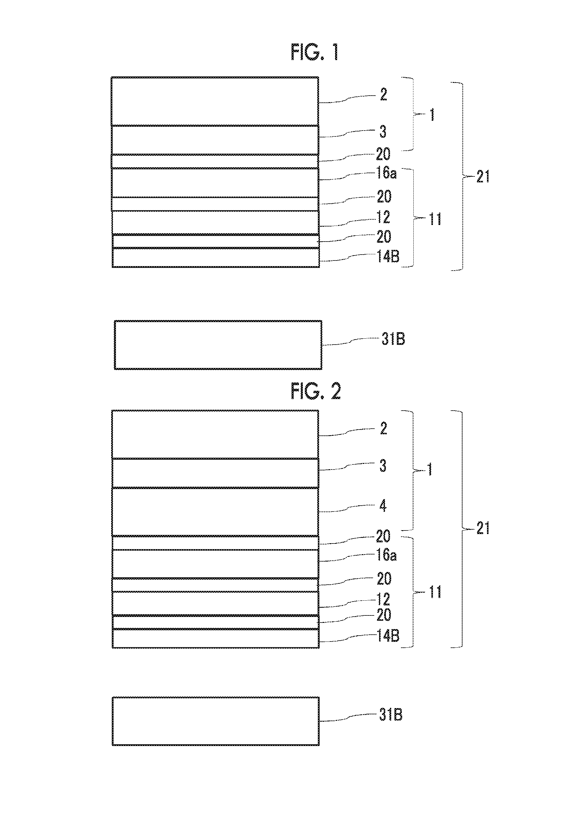
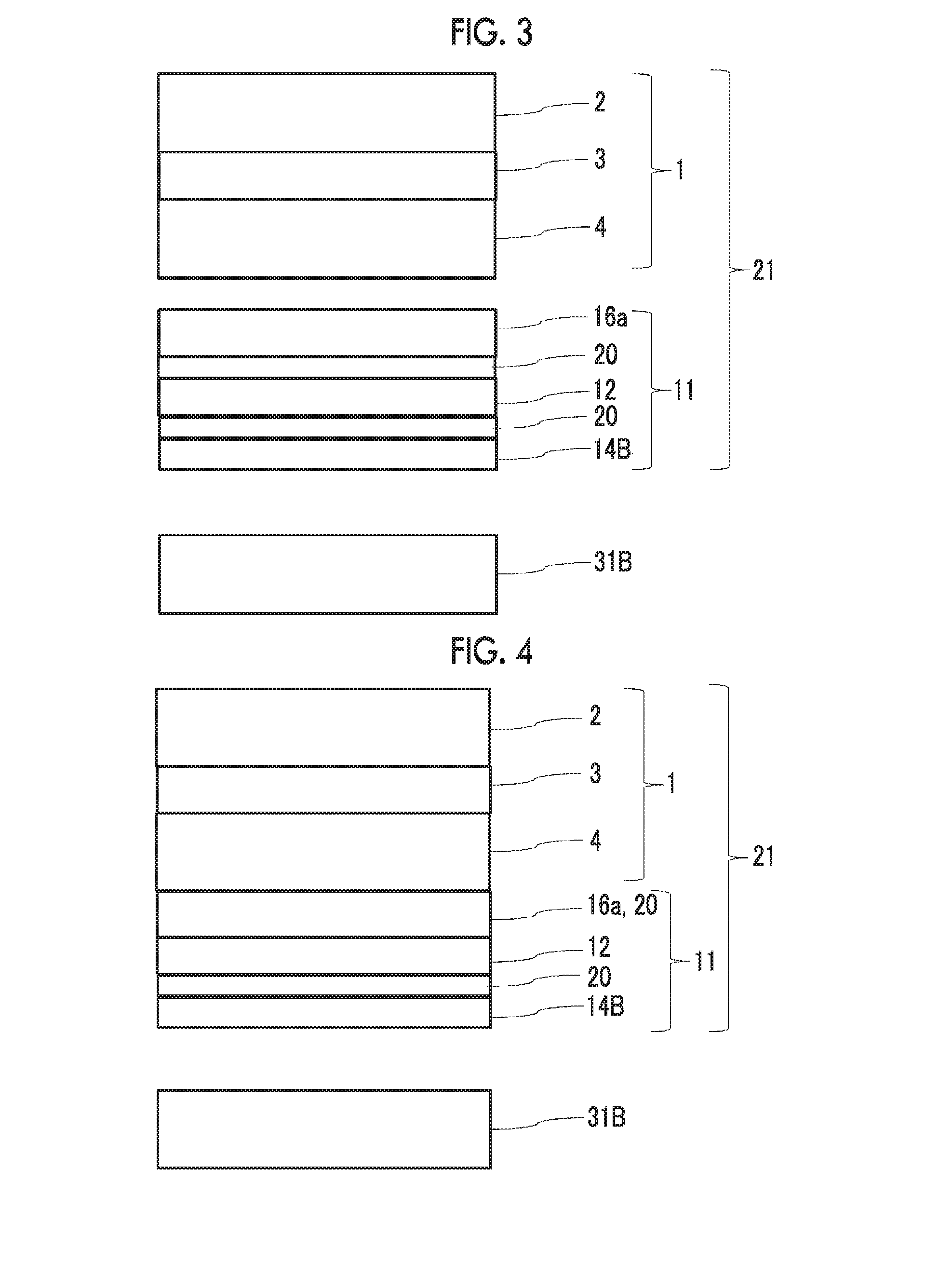
[0053]According to the present invention, it is possible to provide an optical sheet member in which the thickness of the member is thinned by reducing the number of members, the occurrence of brightness unevenness is suppressed by foreign substances mixed into the display devi

Problems solved by technology

In JP3448626B and JP1989-133003A (JP-H01-133003A) in which a light utilization rate is enhanced, a broadband optical recycling function is applied to the white light,

Method used


Image

  • Optical sheet member and image display device using same
  • Optical sheet member and image display device using same
  • Optical sheet member and image display device using same

Examples


Example

Manufacturing Example 1

Preparation of Polarizing Plate

[0313]A retardation film was prepared by using a commercially available cellulose acylate-based film “TD60” (manufactured by Fujifilm Corporation) as a front-side polarizing plate protective film of a backlight side polarizing plate.

[0314]A commercially available cellulose acylate-based film “TD60” (manufactured by Fujifilm Corporation) was used as a rear-side polarizing plate protective film of the backlight side polarizing plate, and a thinner optical sheet member was able to be prepared by using a cellulose acylate-based film having a thickness of preferably less than or equal to 40 μm, and more preferably less than or equal to 25 μm.

[0315]As described in “0219” to “0220” of JP2006-293275A, a polarizer was manufactured, and the retardation film and the polarizing plate protective film described above were bonded to both surfaces of the polarizer, and thus a polarizing plate was manufactured. In addition, when the optical membe...

Example

Manufacturing Example 2

Preparation of Polarizing Plate

[0316]A polarizing plate was manufactured by bonding the retardation film and the polarizing plate protective film onto both surfaces of the polarizer, respectively, by the same method as that in Manufacturing Example 1 except that a long film 1 having a thickness of 40 μm obtained by supplying a pellet of a mixture [Tg of 127° C.] of 90 parts by mass of an acrylic resin having a lactone ring structure {a copolymerization monomer mass ratio=methyl methacrylate / methyl 2-(hydroxymethyl) acrylate=8 / 2, a lactone ring formation rate of approximately 100%, a content ratio of the lactone ring structure of 19.4%, a weight average molecular weight of 133000, a melt flow rate of 6.5 g / 10 minutes (240° C. and 10 kgf), and Tg of 131° C.} and 10 parts by mass of an acrylonitrile-styrene (AS) resin {Toyo AS AS20, manufactured by Toyo-Styrene Co., Ltd.} to a biaxial extruder, and by melting and extruding the pellet at approximately 280° C. into...

Example

Manufacturing Example 3

Preparation of Polarizing Plate

[0317]A polarizing plate was manufactured by bonding the retardation film and the polarizing plate protective film onto both surfaces of the polarizer, respectively, by the same method as that in Manufacturing Example 1 except that a commercially available COP film “Zeonor ZF14” (manufactured by Zeon Corporation) was used as the rear side polarizing plate protective film of the backlight side polarizing plate.

Example 1-A

Formation of Optical Conversion Member

[0318]A quantum dot sheet (a quantum dot material (G,R)) which emitted fluorescent light of green light having a center wavelength of 540 nm and a half-value width of 40 nm and red light having a center wavelength of 645 nm and a half-value width of 30 nm when blue light of a blue light emitting diode was incident thereon was formed as the optical conversion member with reference to JP2012-169271A.

[0319]The obtained quantum dot sheet and the polarizing plate 1 manufactured in ...


PUM


Abstract

An optical sheet member includes a polarizing plate including a polarizer (A); an optical conversion member (D); and a brightness enhancement film including a reflection polarizer (B), in which the brightness enhancement film has a reflection center wavelength range of 400 nm to 500, and the optical conversion member (D) converts a part of blue light which is transmitted through polarizer (B) and is incident on the optical conversion member (D), and has an emission center wavelength range of 400 nm to 500 nm and which has an emission center wavelength range of 500 nm to 600 nm and red light which has an emission center wavelength range of 600 nm to 700 nm, and transmits a part of the blue light. When the optical sheet member is incorporated in an image display device, front brightness, contrast, and a color reproducing region are enhanced, and color unevenness is reduced.

Description

CROSS-REFERENCE TO RELATED APPLICATIONS[0001]This application is a Continuation of PCT International Application No. PCT / JP2014 / 065121, filed on Jun. 6, 2014, which claims priority under 35 U.S.C. Section 119(a) to Japanese Patent Application No. 2013-119670 filed on Jun. 6, 2013. Each of the above applications is hereby expressly incorporated by reference, in its entirety, into the present application.BACKGROUND OF THE INVENTION[0002]1. Field of the Invention[0003]The present invention relates to an optical sheet member and an image display device employing the same.[0004]2. Description of the Related Art[0005]A flat panel display such as a liquid crystal display device (hereinafter, also referred to as an LCD) has been widely used as an image display device having small power consumption and space saving properties over the years. The liquid crystal display device has a configuration in which backlight (hereinafter, also referred to as BL), a backlight side polarizing plate, a liq...

Claims


Application Information

Patent Timeline
IPC IPC(8): G02F1/13363G02B5/30G02F1/1335H01L27/12H01L29/786
CPCG02F1/13363G02B5/305G02B5/3083G02F2001/133614G02F1/133617H01L27/1225H01L29/7869G02F1/133528G02B5/22G02F1/133614
Inventor OHMURO, KATSUFUMISAITOH, YUKITOWATANO, AKIKO
Owner FUJIFILM CORP
Why Eureka
Try Eureka