
Electrical Insulation System

Active Publication Date: 2016-03-31
HITACHI ENERGY SWITZERLAND AG
View PDF3 Cites 0 Cited by
  • Summary
  • Abstract
  • Description
  • Claims
  • Application Information

AI Technical Summary

Benefits of technology

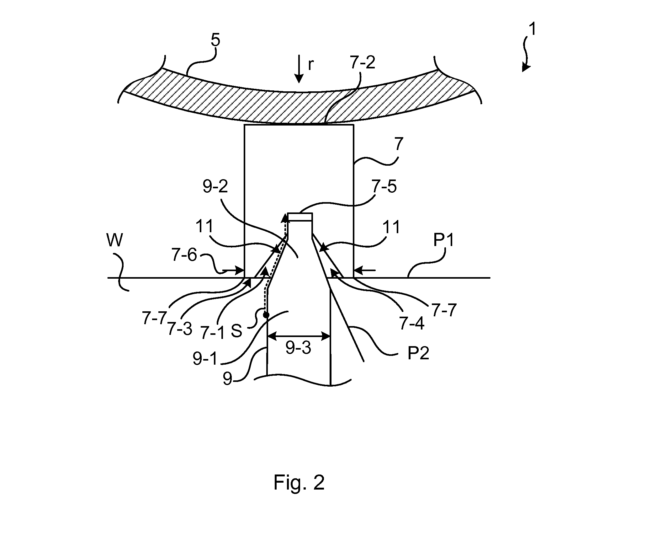
The present disclosure provides an electrical insulation system that reduces the risk of streamers reaching a cylindrical barrier, which can cause electrical breakdown. The system includes a spacer with a groove that captures streamers, regardless of their origin. The tapering of the groove and the fitting end portion makes it difficult for a streamer to jump from the lateral side of the spacer to the outer side of the longitudinal bar at the end face of the second side of the longitudinal bar. The longitudinal bar is made of plastic material and has ribs that extend the propagation distance of streamers, making it more difficult for them to reach the cylindrical insulation barrier. This results in a more compact high voltage inductive device that can handle higher electrical stress without electrical breakdown.

Problems solved by technology

Existing electrical insulation systems do however not provided an adequate protection from streamers propagating from a spacer towards a cylindrical barrier.

Method used


Image

  • Electrical Insulation System
  • Electrical Insulation System
  • Electrical Insulation System

Examples


Embodiment Construction

[0031]The inventive concept will now be described more fully hereinafter with reference to the accompanying drawings, in which exemplifying embodiments are shown. The inventive concept may, however, be embodied in many different forms and should not be construed as limited to the embodiments set forth herein; rather, these embodiments are provided by way of example so that this disclosure will be thorough and complete, and will fully convey the scope of the inventive concept to those skilled in the art. Like numbers refer to like elements throughout the description.

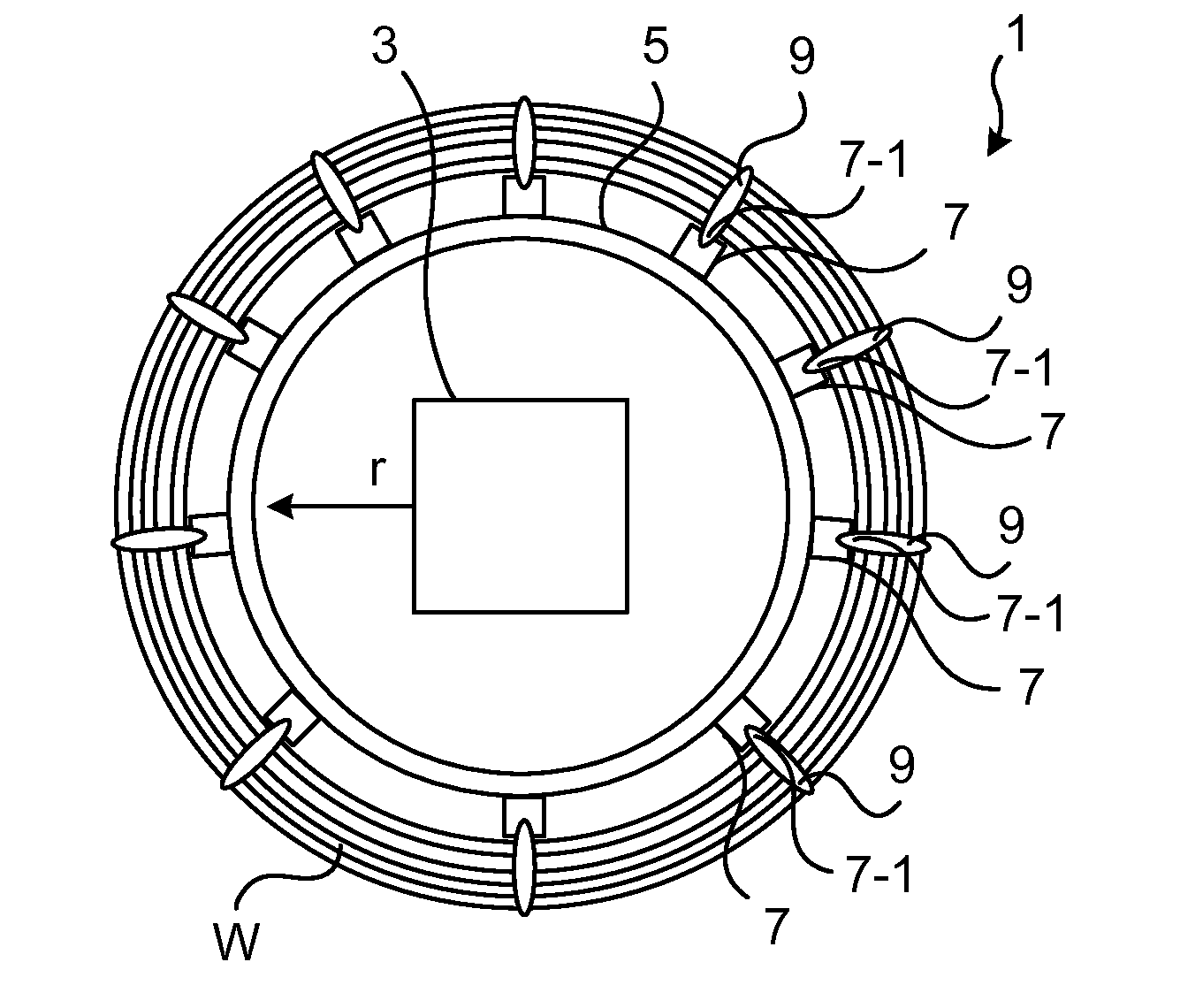
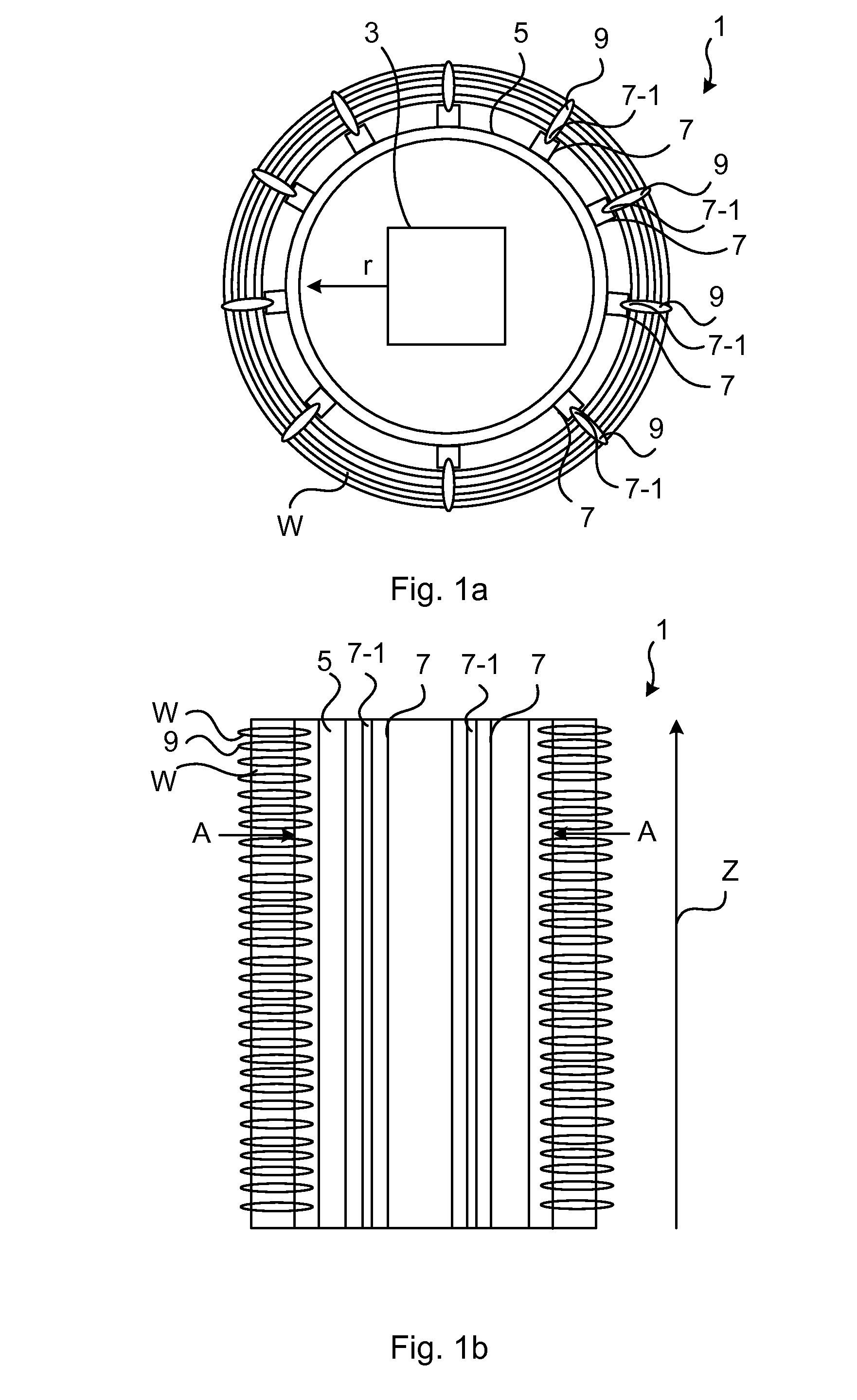
[0032]FIG. 1a depicts an electrical insulation system 1 arranged around a magnetic core 3 of a high voltage inductive device. The electrical insulation system 1 comprises a cylindrical insulation barrier 5 which is to be arranged radially outwards relative to the magnetic core 3, as shown in FIG. 1a. In other words, the cylindrical insulation barrier 5 is arranged outside the magnetic core 3, in the radial direction r, an...


PUM


Abstract

An electrical insulation system for a high voltage inductive device includes a cylindrical insulation barrier defining an axial direction, a longitudinal bar having a main extension in the axial direction, the longitudinal bar arranged to support the cylindrical insulation barrier along the axial direction and to provide spacing in a radial direction, and the longitudinal bar having a first side facing the cylindrical insulation barrier and a second side, opposite the first side, having a groove, and a spacer having a main extension in the radial direction, the spacer being arranged to provide spacing in the axial direction, the spacer having a groove fitting end portion. The longitudinal bar is adapted to receive the groove fitting end portion of the spacer in the groove, and wherein the spacer is dimensioned so relative to the groove that the groove captures any streamer propagating from the spacer towards the cylindrical insulation barrier.

Description

FIELD OF THE INVENTION[0001]The present disclosure generally relates to inductive devices. In particular it relates to an electrical insulation system for a high voltage inductive device.BACKGROUND OF THE INVENTION[0002]In oil insulated inductive devices, such as power transformers, mineral oil is typically used as an insulating fluid between inner parts subject to different electric potentials. The inner parts of an inductive device normally comprise a magnetic core, windings, and an electrical insulation system which provides insulation between parts having different electric potential. In particular, in the main duct of an inductive device a certain distance in oil should be kept to avoid dielectric breakdown during tests and service.[0003]One typical solution of the insulation between windings in the main duct for core type designs implies the use of cylindrical barriers made of e.g. pressboard to divide oil spaces in the radial direction. This subdivision greatly improves the d...

Claims


Application Information

Patent Timeline
IPC IPC(8): H01B17/56H01F27/32
CPCH01F27/325H01B17/56H01F27/2871H01F27/324
Inventor ERIKSSON, ANDERS, BOGAFVERT, UNODEL, REAL, JOSE-LUISHAJEK, JAN
Owner HITACHI ENERGY SWITZERLAND AG
Learn More