Dynamic and Adaptive Configurable Power Distribution System

a power distribution system and dynamic technology, applied in non-electric variable control, process and machine control, instruments, etc., can solve the problems of affecting the entire distribution system, affecting the configuration new problems in the operation and control of the distribution system, so as to increase the stability guarantee and good measure of stability level

Active Publication Date: 2016-04-07
MITSUBISHI ELECTRIC RES LAB INC
View PDF4 Cites 42 Cited by
  • Summary
  • Abstract
  • Description
  • Claims
  • Application Information

AI Technical Summary

Benefits of technology

[0021]The SCPM and SCEM describe the transient security for a particular configuration of the distribution system. With adequate SCPM and SCEM, the system can tolerate most unexpected load deviations and errors in forecasting renewable resources. The margins are a good measure of stability level of the distribution system without time domain analysis, so the method can be implemented in real-time. Extra conservativeness introduced by the SCEM and SCPM increases the stability guarantee.

Problems solved by technology

Because conventional distribution systems have no or very limited generation resources, any outage at or upstream from a substation affects the entire distribution systems.
The outages can be due to generator and transmission line failures, short-circuit, overloads, climate and severe weather conditions, and geological events.
DRR change power consumption patterns that potentially could affect how the distribution system is configured.
This opens up new issues for the operation and control of the distribution systems.
The first issue is that many of the renewable power sources are weather and time dependent.
The second issue is that some renewable resource, such as solar panels, output DC current.
However, inverter based generation sources have no or less inertia than conventional synchronous generators.
Characteristically, the above prior art methods generally reconfigure the distribution system only in response to unanticipated events.
Those solutions do not provide adequate solutions for distribution systems with a large number of renewable DG and more energy aware consumers using DRR.

Method used


Image

  • Dynamic and Adaptive Configurable Power Distribution System
  • Dynamic and Adaptive Configurable Power Distribution System
  • Dynamic and Adaptive Configurable Power Distribution System

Examples


Embodiment Construction

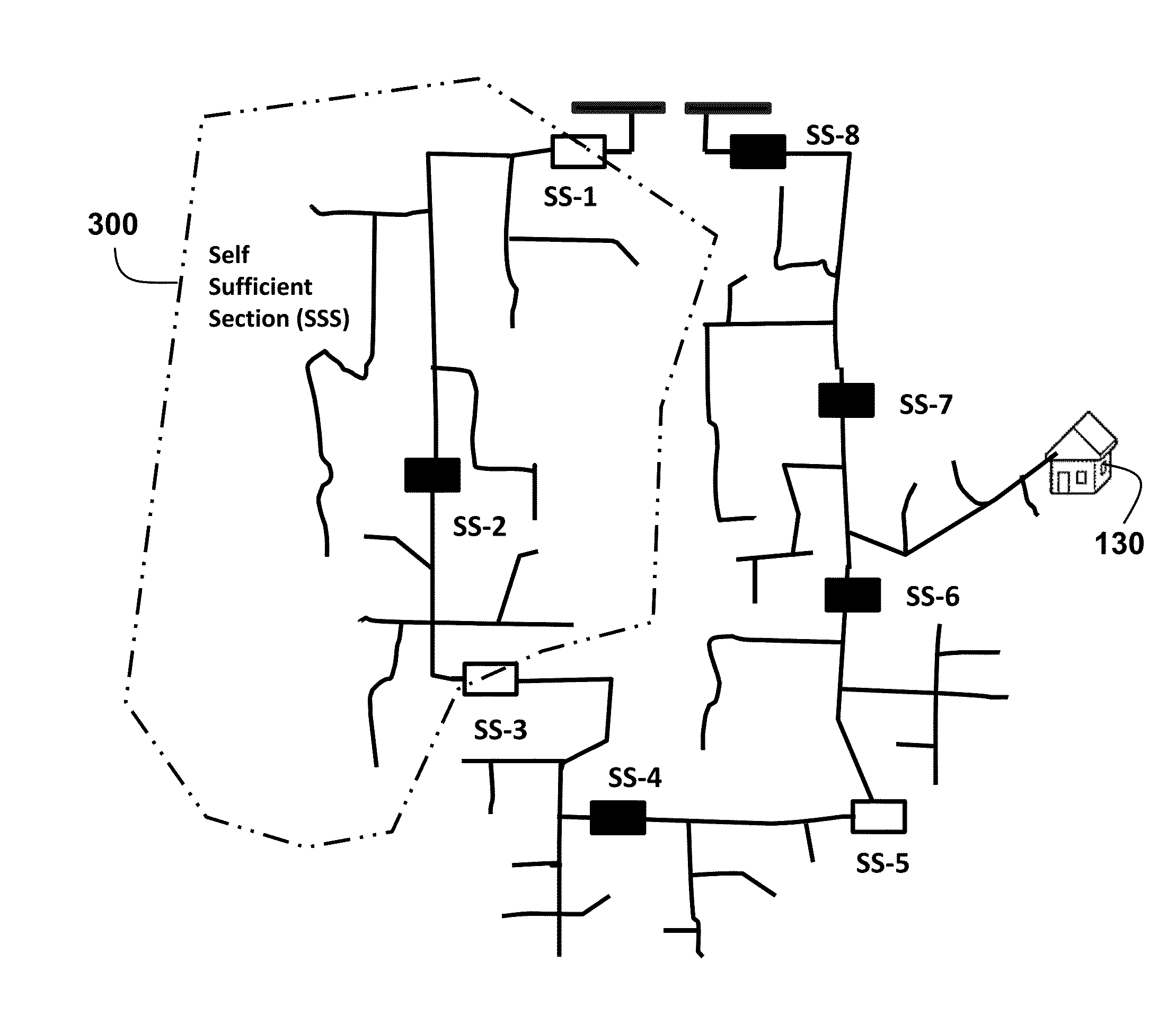
[0030]Distribution System Configuration

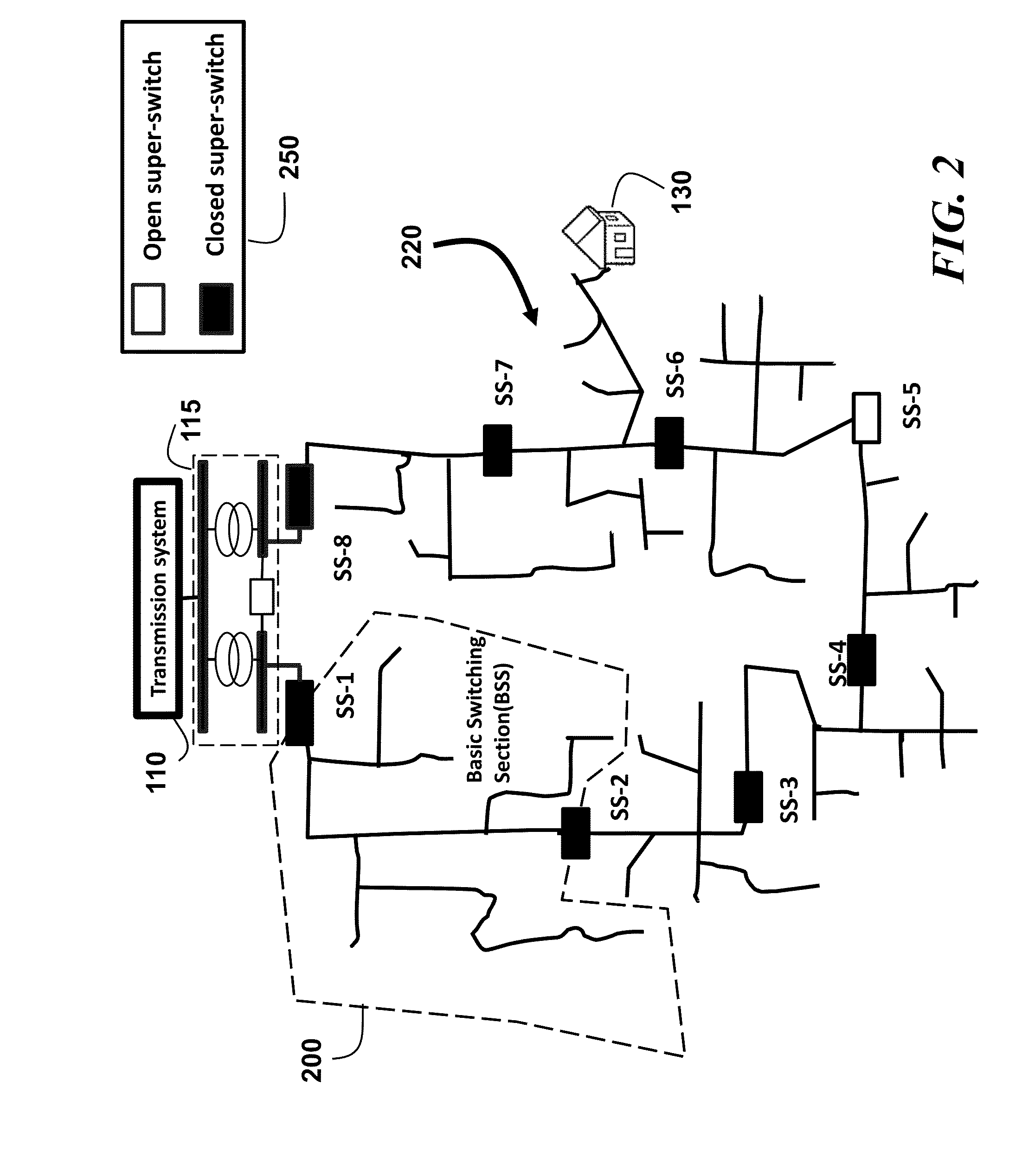
[0031]As shown in FIG. 2, a power distribution system 220 according to embodiments of the invention can use a radial topology with a tree structure. Other topologies, such mesh, looped, and tied ring are also possible.

[0032]In the system, conventional sectionalizing and tie switches are replaced with, e.g., solid state super-switches 250. In FIG. 2, there are eight super-switches. The switches SS-1 and SS-8 are connected to the transmission system (main grid) 110. These switches can open and close at a relatively high frequently when compared with conventional electromechanical switches. The switches can be equipped with phasor measurement units (PMU) or synchrophasors to enable real-time monitoring and control. The PMU can supply voltages and currents measurements at high sampling rate, for examples, 60 samples per second.

[0033]Basic Switching Sections

[0034]Using the super-switches the distribution system can be configured with basic switching...


PUM


Abstract

A power distribution system is dynamically and adaptively configured in real-time to improve energy efficiency, reliability and power quality, particularly if the system includes renewable sources and storages. An optimal multi-objective scheduling and partitioning method is provided to partition the system into self-sufficient sections (SSS) through optimally combination of adjacent basic switching sections (BSS). The SSSs enable system operating at a lower cost, with less power losses, more energy efficiency, improved power quality, and sufficient transient security. The method uses two storage based transient security indices, storage compensation power margin (SCPM) and storage compensation energy margin (SCEM) evaluate the transient stability margin of distribution system. A minimal stability margin is used to ensure that the system remains stable when subject to large unexpected load deviations.

Description

FIELD OF THE INVENTION[0001]The present invention relates generally to electric power systems, and more particularly to a dynamic and adaptive configurable power distribution system.BACKGROUND OF THE INVENTION[0002]As shown in FIG. 1 for a conventional electric power system, power is fed from a transmission system 110 to consumers 130, via a substation 115 and a distribution system 120 (electric utility). Because conventional distribution systems have no or very limited generation resources, any outage at or upstream from a substation affects the entire distribution systems. The outages can be due to generator and transmission line failures, short-circuit, overloads, climate and severe weather conditions, and geological events. Usually, a topology of the distribution system is radial and unidirectional, with currents flowing from the substation through the breakers and switches to the consumers.[0003]Each downstream feeder can have a circuit breaker at a feeder head, several normall...

Claims


Application Information

Patent Timeline
Patent Type & Authority Applications(United States)
IPC IPC(8): H02J3/14
CPCH02J2003/143H02J3/14H02J3/28H02J3/381Y02B70/3225Y04S10/30Y04S20/222H02J2203/20H02J13/00002H02J2300/10H02J2300/20H02J13/00034Y02E40/70Y02E60/00Y04S10/00Y04S10/22Y04S40/20H02J2300/24H02J3/241H02J3/0075H02J2310/58H02J3/144H02J2310/54Y02E10/56Y04S10/123Y04S20/12Y02B70/30Y02B90/20Y04S20/00Y04S20/242
Inventor SUN, HONGBOWANG, YISHEN
Owner MITSUBISHI ELECTRIC RES LAB INC
Why Eureka
Try Eureka