Method to Generate Multilevel Inverter Modulation Control Signals

a multi-level inverter and modulation control technology, applied in the field of power inverters, can solve the problems of significant computation complexity, power semiconductors that cannot withstand reduced voltages, and cannot employ conventional vsi in the high power range. achieve the effect of simple and systematic approach

Active Publication Date: 2016-04-07
MITSUBISHI ELECTRIC RES LAB INC
View PDF8 Cites 12 Cited by
  • Summary
  • Abstract
  • Description
  • Claims
  • Application Information

AI Technical Summary

Benefits of technology

[0013]The embodiments of the invention provide a space vector representation in a three phase coordinate systems and some of its general properties. These properties lead to an extremely simplified, systematic approach in computing the coefficients of the triplets and pulse width modulation duty cycles. Specifically, a method generates space vector modulation signals for a multi-level power inverter using space vector pulse width modulation (SVPWM). A reference voltage and a triangle region for the reference voltage are determined. Vertices for a space vector that is closest to the reference voltage is outputted. Then, the vertices are adjusted so that the space vector is in a valid region of the triangle region. Lastly, the space vector modulation signals a, b, and c corresponding to the space vector in the valid region are outputed.

Problems solved by technology

However, high voltage stress, high harmonic distortions, and instantaneous voltage change rate are some of the challenges facing a two level inverters.
The commutation of the switches permits the addition of the capacitor voltages, which reach high voltage at the output, while the power semiconductors can only withstand reduced voltages.
Actually, it is not still possible to employ conventional VSI in the high power range due to commutation difficulties and reverse recovery high voltages.
The computation complexity is significant because of the non-linear trigonometrical operations.
It also suffers high latency when the number of levels becomes high.

Method used


Image

  • Method to Generate Multilevel Inverter Modulation Control Signals
  • Method to Generate Multilevel Inverter Modulation Control Signals
  • Method to Generate Multilevel Inverter Modulation Control Signals

Examples


Embodiment Construction

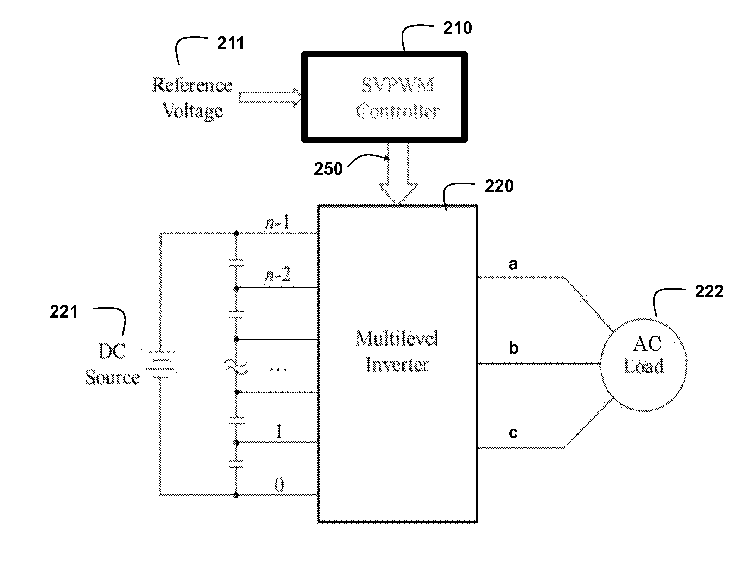
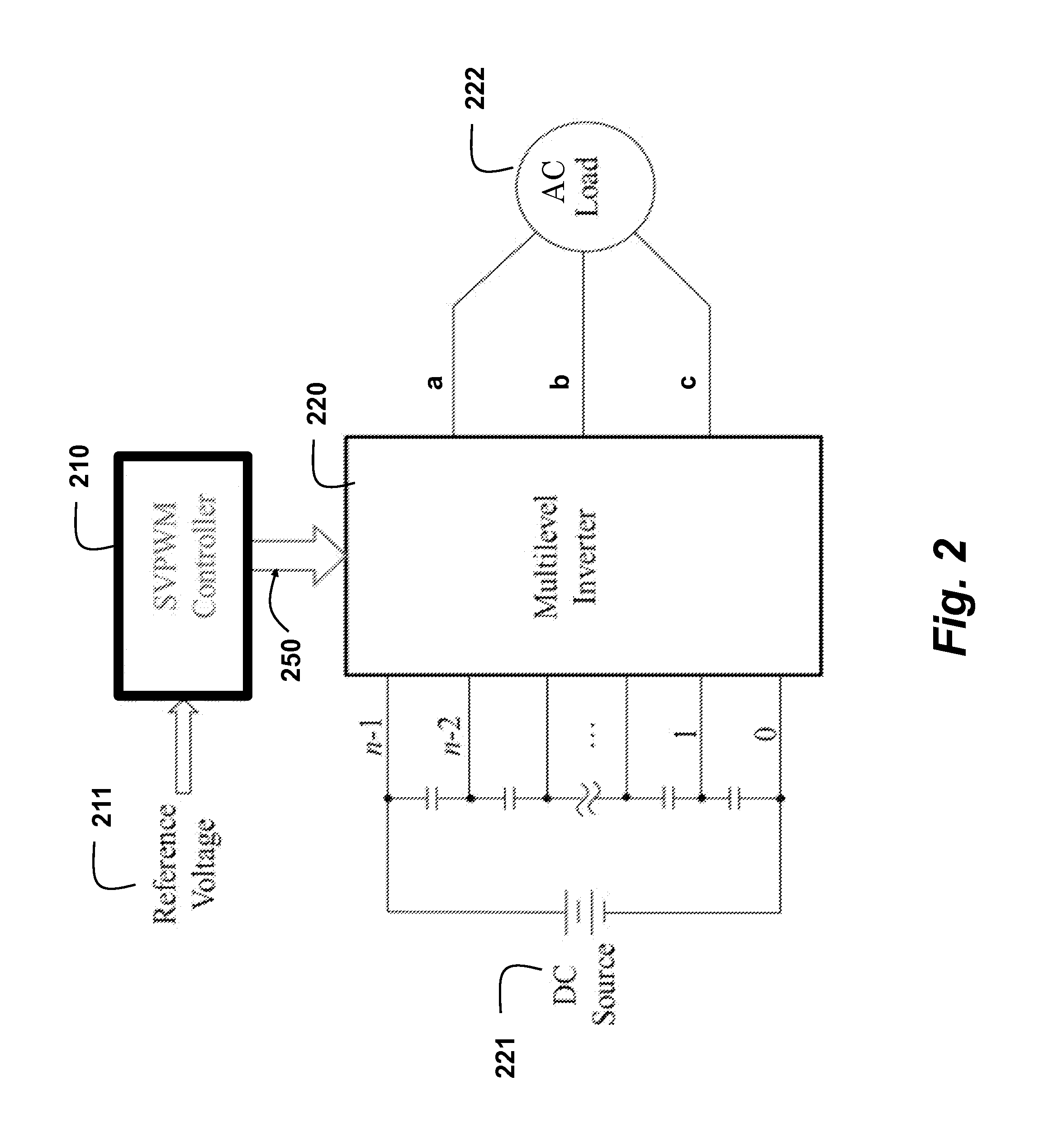
[0022]FIG. 2 shows a space vector pulse width modulation (SVPWM) controller 210 for a neutral-point clamped (NPC) inverter 220. The controller take a reference voltage 211 as input. The outputs of the SVPWM are space vector modulation signals a, b, and c 250, where a, b, and c correspond to the three phase of the AC signal. The inverter is connected between a DC source 221 and an AC load 222. The source can have N levels (0, 1, . . . , n−1). In contrast to the prior art where the number of levels is generally 2, the number of levels that can be specified for the inverter according to the embodiments can be arbitrary, e.g., 5, 7 or 25.

[0023]Space Vector Pulse Width Modulation (SVPWM) in 3 Phase Coordinate System

[0024]The most commonly used coordinate system to represent a vector in a two dimensional, or three dimensional space is a Cartesian coordinate system, where a vector V can be decomposed into the summation of vectors that are orthogonal to each others, i.e., v={right arrow ove...


PUM


Abstract

A method generates space vector modulation signals for a multi-level power inverter using space vector pulse width modulation (SVPWM). A reference voltage and a triangle region for the reference voltage are determined. Vertices for a space vector that is closest to the reference voltage is outputted. Then, the vertices are adjusted so that the space vector is in a valid region of the triangle region. Lastly, the space vector modulation signals a, b, and c corresponding to the space vector in the valid region are outputed.

Description

FIELD OF THE INVENTION[0001]This invention relates generally to power invertors, and more particularly to controlling multilevel power inverters.BACKGROUND OF THE INVENTION[0002]Power inverters can greatly improve the overall efficiency, performance and quality of signals of a power system. Conventionaly, two-level inverters are widely used for their low cost and minimal complexity. However, high voltage stress, high harmonic distortions, and instantaneous voltage change rate are some of the challenges facing a two level inverters.[0003]Multilevel (ML) inverters can potentially address these challenges. ML inverters can be used for high-power, high voltage applications due to inherent advantages, such as reduced voltage stress, lower harmonics, lower instantaneous voltage change rate dv / dt and lower common-mode voltage. Modular multilevel converters are used for renewable energy applications. ML inverters are extensively used in high-power applications with medium voltage levels. Th...

Claims


Application Information

Patent Timeline
Patent Type & Authority Applications(United States)
IPC IPC(8): H02M7/537H02M1/12
CPCH02M1/12H02M7/537H02M7/487H02M7/53876
Inventor DUAN, CHUNJIETEO, KOON HOOMA, RUI
Owner MITSUBISHI ELECTRIC RES LAB INC
Why Eureka
Try Eureka