Method and Circuit for the Improved Use of Capacitance in an Intermediate Circuit

a capacitance and intermediate circuit technology, applied in the field of intermediate circuits, can solve problems such as space and cost saving, and achieve the effect of low loss

Active Publication Date: 2016-04-07
ROBERT BOSCH GMBH +1
View PDF7 Cites 0 Cited by
  • Summary
  • Abstract
  • Description
  • Claims
  • Application Information

AI Technical Summary

Benefits of technology

[0015]Also preferredly, the compensation unit has a direct-voltage/direct-voltage (DC/DC) converter which is configured to feed electric energy into the ground connection of the capacitance. Since a DC/DC converter has low

Problems solved by technology

This allows a capacitor of lesser size to be used and thus considerable space and cost savin

Method used


Image

  • Method and Circuit for the Improved Use of Capacitance in an Intermediate Circuit
  • Method and Circuit for the Improved Use of Capacitance in an Intermediate Circuit
  • Method and Circuit for the Improved Use of Capacitance in an Intermediate Circuit

Examples


Embodiment Construction

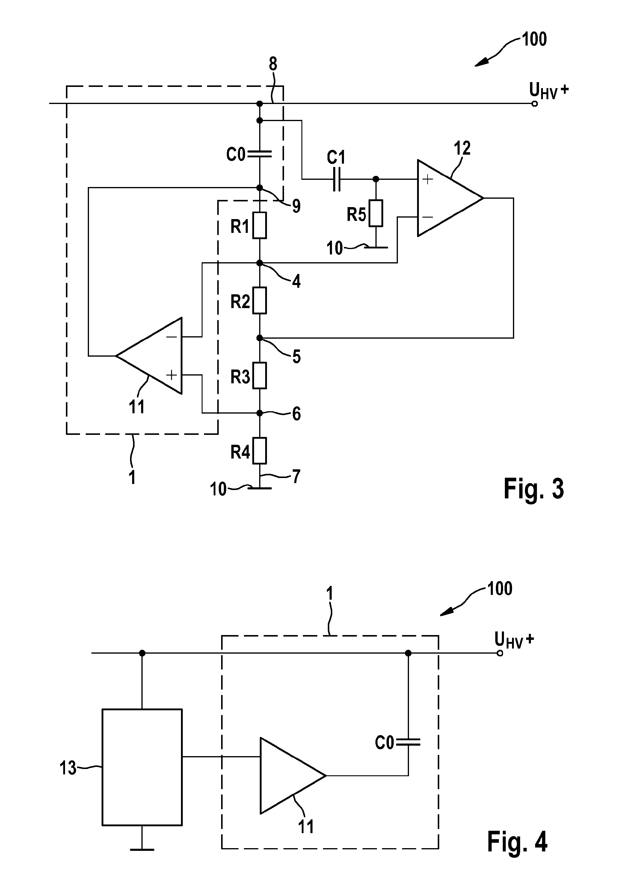
[0027]FIG. 3 shows a circuit 100 according to the present invention as can be used for smoothing voltage ripple in an on-board high-voltage (HV) direct-voltage system. A connection point 8 coincides with the high-voltage potential UHV+ of the on-board direct-voltage system and with a high-voltage connection of the capacitance C0. At the ground side, a connection point 9 is provided at which a first resistor R1 is connected. On the other side, the resistor R1 is connected to a second resistor R2 at a connection point 4. On the other side, the second resistor R2 is connected to a third resistor R3 at a connection point 5. On the other side, the third resistor R3 is connected to a fourth resistor R4 at a connection point 6. On the other side, the fourth resistor R4 is connected to a connection point 7 which coincides with electrical ground 10. At the connection point 8, a detection unit comprising a capacitor C1 and a fifth resistor R5 connected to ground 10 is provided. Between the ca...


PUM


Abstract

The disclosure relates to a method and a circuit for the improved use of a capacitance in an intermediate circuit. According to the disclosure, a change in a voltage in an intermediate circuit is detected and electrical energy is actively provided depending on the change in the electrical variable in order to compensate the change. According to the disclosure, a capacitance used in the intermediate circuit can end up significantly smaller if the electrical energy fed in is used, in that the voltage of the capacitance is supported by a current fed into the capacitance on the earth side.

Description

PRIOR ART[0001]The present invention relates to a method and to a circuit for the improved use of a capacitance in an intermediate circuit. In particular, the present invention relates to intermediate circuits for on-board automobile energy systems in which voltage ripples can occur on a line between an energy store and an inverter at the engine.[0002]The increased electrification of the individual traffic has led to the fact that in electrically drivable vehicles, distinctly higher voltages occur (in the 400 V range and higher) and must be processed, than have occurred in on-board vehicle systems until a few years ago. Whilst energy is stored as direct voltage in a (mostly electrochemical) energy store, an inverter is mostly used (direct-voltage / alternating-voltage converter) for supplying the electrical motor (or generator) with (three-phase) alternating voltage or transferring alternating voltage from the (generator-driven) motor into the electrochemical energy store. By means of...

Claims


Application Information

Patent Timeline
IPC IPC(8): H02M7/537
CPCH02M7/537H02M5/45H02M5/297H02M1/15B60L50/51Y02T10/70H02M5/2932
Inventor BUTZMANN, STEFAN
Owner ROBERT BOSCH GMBH
Why Eureka
Try Eureka