Method and apparatus for the rapid delivery of heavy plates from a rolling mill

a technology of heavy plate and rolling mill, which is applied in the direction of metal rolling arrangement, tensioning/braking arrangement, manufacturing tools, etc., can solve the problems of uneconomical and/or impossible production of limited-width hot strips, and achieve the effects of short cycle time, high speed and reliable storag

Inactive Publication Date: 2016-04-14
PRIMETALS TECH AUSTRIA GMBH
View PDF15 Cites 11 Cited by
  • Summary
  • Abstract
  • Description
  • Claims
  • Application Information

AI Technical Summary

Benefits of technology

[0014]One object of this invention is to specify a method and an apparatus for the delivery of plates from a combined casting and rolling plant, wherein even

Problems solved by technology

Production of limited-width hot strip is uneconomical and/or impossible.
However, these appa

Method used


Image

  • Method and apparatus for the rapid delivery of heavy plates from a rolling mill
  • Method and apparatus for the rapid delivery of heavy plates from a rolling mill
  • Method and apparatus for the rapid delivery of heavy plates from a rolling mill

Examples


first embodiment

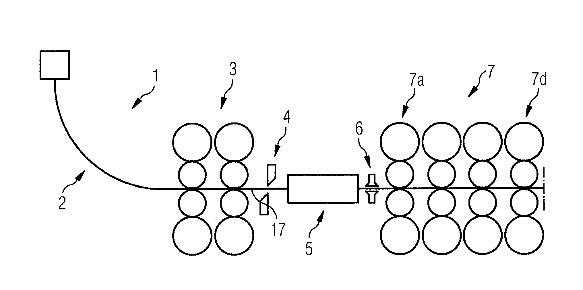
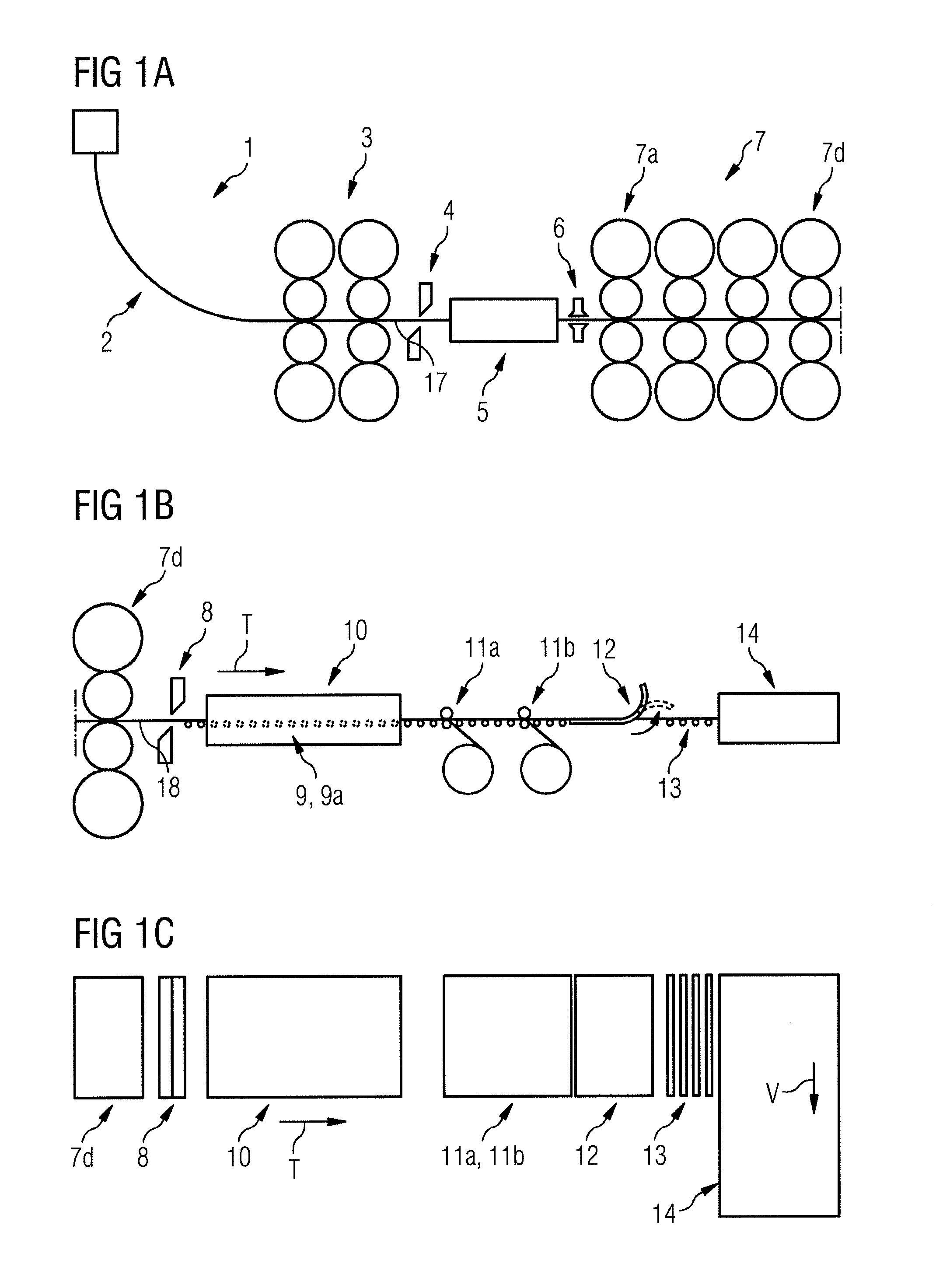
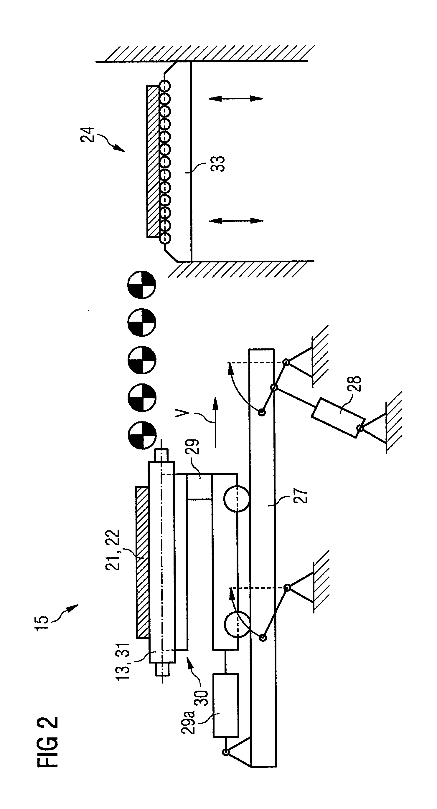
[0093]FIGS. 2 and 3 show a first embodiment variant of a delivery device 14 for the delivery of heavy steel plates from the ESP combined casting and rolling plant as per FIGS. 1A to 1C.

[0094]The delivery device 14 comprises a roller table 13 on which plates 21, 22 can be transported in the direction of transport T, means in the form of the rear limit stop 26a for storing a first plate 21 and means in the form of the forward limit stop 26b for storing a second plate 22 on the roller table 13, and a lateral conveyor 15 for the concurrent delivery of two plates 21, 22 transversely relative to the direction of transport T onto a storage location 24. The roller table 13 has a plurality of driven 9a table rollers 31; non-driven table rollers may also be present. According to the illustration in FIG. 3, two plates 21 and 22 are situated one behind the other on the roller table 13 before the delivery.

[0095]Before the actual delivery of the plates 21, 22 in the delivery device 14, the endles...

second embodiment

[0109]FIG. 5 shows a second embodiment variant of the lateral conveyor 15. The lateral conveyor 15 comprises a gripper 25 which is arranged to the left and right of the plates 21, 22 for the purpose of clamping the plates, and a swiveling unit 32 for swiveling the plates about an axis of rotation D which is oriented parallel to the direction of transport T.

[0110]Once the plates 21, 22 have been clamped by the gripper 25, the swiveling unit 32 is swiveled through approximately 180°, thereby moving the plates from the position illustrated on the left to that illustrated on the right. The plates 21,22 are then released by the gripper 25 and stored on the storage table 33. After storage of the plates, the swiveling unit 32 is swiveled back to the starting position, such that a plurality of plates can be delivered again.

[0111]Parts A) to F) of FIG. 6 show a schematic illustration of a delivery device 14 comprising two lateral conveyors 15, 15′, which are arranged one behind the other, du...


PUM

PropertyMeasurementUnit
Lengthaaaaaaaaaa
Thicknessaaaaaaaaaa
Volumeaaaaaaaaaa

Abstract

A method and device for rapid discharging of metallic plates (21, 22) particularly thick plates, from a rolling mill, to enable secure discharge of relatively short plates (21, 22) from the rolling mill at high velocity and low cycle times by transporting a first plate (21) on a roller bed (9, 13) in the transport direction (T), and preferably the first plate (21) is accelerated in the transport direction (T); depositing the first plate (21) on the roller bed (9, 13); transporting a second plate (22) on the roller bed (9, 13) in the transport direction (T); depositing the second plate (22) in the transport direction before the first plate (21) on the roller bed (9, 13); and discharging the first and the second plates (21, 22) from the roller bed (9, 13) onto a storage (24), wherein the discharging occurs crosswise to the transport direction (T).

Description

CROSS-REFERENCE TO RELATED APPLICATIONS[0001]The present application is a 35 U.S.C. §§371 national phase conversion of PCT / EP2014 / 056560, filed Apr. 2, 2014, which claims priority of Austrian Patent Application No. A50339 / 2013, filed May 21, 2013, the contents of which are incorporated by reference herein. The PCT International Application was published in the German language.TECHNICAL FIELD[0002]The present invention relates to a method and an apparatus for the rapid delivery of metallic plates made from heavy plate from a rolling mill.BACKGROUND OF THE INVENTION[0003]A plate which is made from heavy plate is simply referred to herein as a plate. It is understood in this application to mean a metallic plate having a thickness of between 8 mm and 250 mm, a width>900 mm and a length≧3 m (cf. Document 570, “Grobblech—Herstellung and Anwendung”, Steel Information Center, Düsseldorf, 1st Edition 2001).[0004]The invention relates to a method for delivery of metallic plates, preferably...

Claims


Application Information

Patent Timeline
IPC IPC(8): B21B39/02
CPCB21B39/02B21B1/46B21B13/22B22D11/12B21B1/463B21B37/76B21B39/004B21B39/088B21B39/12B21B45/0218B21B2275/06B21B39/00
Inventor LINZER, BERNDPEITL, WOLFGANGYANG, BOZAHEDI, MICHAEL
Owner PRIMETALS TECH AUSTRIA GMBH
Why Eureka
Try Eureka