Imaging device and three-dimensional-measurement device

a three-dimensional measurement and imaging device technology, applied in the field of imaging devices, can solve the problems of inability to perform ranging, and achieve the effect of accurate specification of laser radiation position and reliable ranging

Inactive Publication Date: 2016-04-14
FUJIFILM CORP
View PDF7 Cites 13 Cited by
  • Summary
  • Abstract
  • Description
  • Claims
  • Application Information

AI Technical Summary

Benefits of technology

[0023]According to the invention, the second imaging unit images the second range including the radiation position of the laser beam within the first range imaged by the first imaging unit to generate the second image, and the laser radiation position specification unit searches for a portion matching the second image in the first image to specify the radiation position in the first image; thus, it is possible to accurately specify the laser radiation position.
[0024]According to the invention, the laser beam can be radiated in an arbitrary direction within the first range; thus, it is possible to reliably perform ranging to a subject having a hollow.

Problems solved by technology

As described in JP2004-205222A, if the laser radiation position is fixed in order to allow ranging of the determined position in the imaging range, when an object does not exist at the ranging position, a reflected beam of the laser beam is not received, and it is not possible to perform ranging.
For example, when a subject (triumphal arch) shown in FIG. 18 is an imaging target, a center position 101 as a laser radiation position in an imaging range 100 becomes a hollow portion of the subject, and the laser beam is not reflected; thus, it is not possible to perform ranging.

Method used


Image

  • Imaging device and three-dimensional-measurement device
  • Imaging device and three-dimensional-measurement device
  • Imaging device and three-dimensional-measurement device

Examples


first embodiment

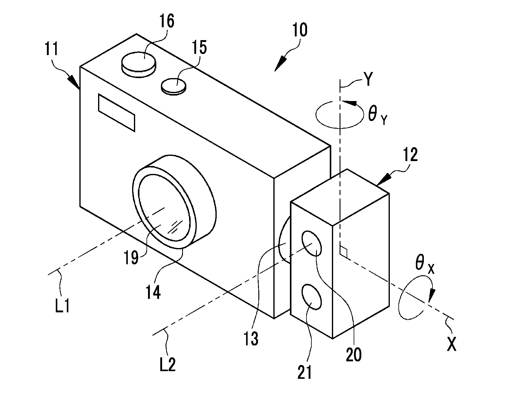
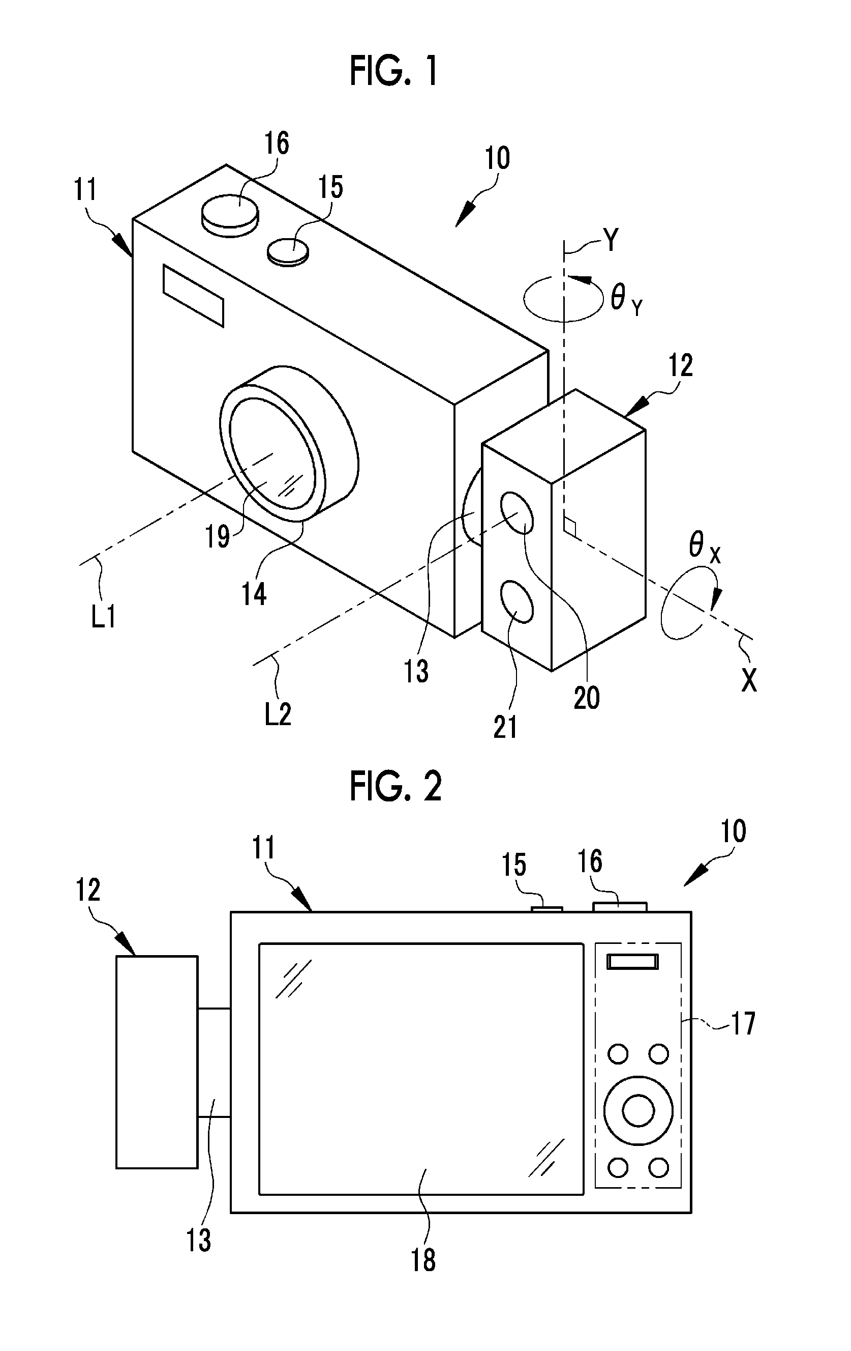
[0044]In FIGS. 1 and 2, a digital camera 10 has a camera body 11, a laser ranging unit 12, and a hinge unit 13. The camera body 11 performs imaging of a subject. The laser ranging unit 12 measures the distance to the subject. The hinge unit 13 holds the laser ranging unit 12 so as to be rotatable with respect to the camera body 11. In the camera body 11, a lens barrel 14, a power button 15, a release button 16, a setting operation unit 17, a display unit 18, and the like are provided.

[0045]The lens barrel 14 is provided on the front surface of the camera body 11, and holds an imaging lens 19 having one or a plurality of lenses. The power button 15 and the release button 16 are provided on the top surface of the camera body 11. The setting operation unit 17 and the display unit 18 are provided on the rear surface of the camera body 11.

[0046]The power button 15 is operated for switching on / off the power supply (not shown) of the digital camera 10. The release button 16 is operated for...

second embodiment

[0079]In FIG. 9, a digital camera 50 of a second embodiment includes an angle detection unit 51 which detects the angle of the laser ranging unit 12 with respect to the camera body 11 (that is, the angles θX and θY between the optical axis L1 and the optical axis L2). The angle detection unit 51 supplies the detected angles θX and θY to the laser radiation position specification unit 34. The angle detection unit 51 is constituted of a potentiometer or the like.

[0080]In this embodiment, the laser radiation position specification unit 34 determines a rough position of the laser radiation position in the first image D1 based on the angles θX and θY detected by the angle detection unit 51, and the position is set as an initial position for performing matching of the pattern of the second image D2 to the first image D1.

[0081]Specifically, as shown in FIG. 10, the laser radiation position specification unit 34 calculates the rough position (initial position 52) of the laser radiation posi...

third embodiment

[0087]In FIGS. 14 and 15, a digital camera 70 of a third embodiment is provided with a laser ranging unit 72 in a camera body 71. The camera body 71 has the same configuration as the camera body 11 of the first embodiment. The laser ranging unit 72 has a configuration different from the configuration of the laser ranging unit 12 of the first embodiment only in that a reflection mirror 73 is provided between the first objective lens 40 and the dichroic mirror 41, and the optical axis L2 is bent by the reflection mirror 73.

[0088]The reflection mirror 73 is a mirror device having a movable reflection surface, and is, for example, a digital mirror device (DMD). The reflection mirror 73 changes the inclination angle of the reflection surface and the direction of the optical axis L2 under the control of the second control unit 47. The radiation direction of the laser beam LB and the position of the second imaging range R2 are changed in conjunction with a change in the optical axis L2.

[00...


PUM


Abstract

A laser ranging unit is rotatably attached to a camera body by a hinge unit. The camera body has a first imaging unit and a laser radiation position specification unit. The laser ranging unit has a laser radiation unit, a laser receiving unit, a second imaging unit, and a distance calculation unit. The first imaging unit images a first range to generate a first image. The laser radiation unit is able to radiate a laser beam in an arbitrary direction within the first range. The laser receiving unit receives a reflected beam of the laser beam. The second imaging unit images a second range including a radiation position of the laser beam within the first range to generate a second image. The laser radiation position specification unit searches for a portion matching the second image in the first image to specify the radiation position in the first image. The distance calculation unit calculates the distance to the radiation position based on the time of receiving the reflected beam.

Description

CROSS-REFERENCE TO RELATED APPLICATIONS[0001]This application is a Continuation of PCT International Application No. PCT / JP2014 / 066651 filed on Jun. 24, 2014, which claims priority under 35 U.S.C. §119(a) to Japanese Patent Application No. 2013-147636 filed Jul. 16, 2013. The above application is hereby expressly incorporated by reference, in its entirety, into the present application.BACKGROUND OF THE INVENTION[0002]1. Field of the Invention[0003]The present invention relates to an imaging device having a laser ranging unit and a three-dimensional-measurement device equipped with the imaging device.[0004]2. Description Related to the Prior Art[0005]An imaging device, such as a digital camera, having a laser ranging unit which radiates a laser beam toward a subject and receives a reflected beam of the laser beam to determine the distance (ranging information) to the subject is known (see JP2004-205222A and JP2001-317915A).[0006]An imaging device described in JP2004-205222A includes ...

Claims


Application Information

Patent Timeline
Patent Type & Authority Applications(United States)
IPC IPC(8): G01S7/48G01S17/89G01S17/42G01S17/86
CPCG01S7/4808G01S17/89G01S17/42G01C3/06G02B7/40G03B29/00G03B35/02G01S17/08G03B17/56G01S17/86H04N23/50H04N23/56H04N23/51H04N23/661H04N23/634
Inventor MASUDA, TOMONORITAMAYAMA, HIROSHIWATANABE, MIKIOISHIYAMA, EIJIHAYASHI, DAISUKEMAKISHIMA, SUGIO
Owner FUJIFILM CORP
Why Eureka
Try Eureka