Photovoltaic systems

a photovoltaic and solar panel technology, applied in the direction of photovoltaics, solar heat collectors for particular environments, heat collector mounting/support, etc., can solve the problems of numerous wired or otherwise contacting electrical connections, difficult, expensive and time-consuming to make, and weathering of the pv unit in whatever form it takes

Active Publication Date: 2016-04-14
ZINNIATEK
View PDF3 Cites 66 Cited by
  • Summary
  • Abstract
  • Description
  • Claims
  • Application Information

AI Technical Summary

Benefits of technology

[0210]In this specification where reference has been made to patent specifications, other external documents, or other sources of information, this is generally for the purpose of providing a context for discussing the features of the invention. Unless specifically stated otherwise, reference to such external documents is not to be construed as an admission that such documents, or such sources of information, in any jurisdiction, are prior art, or form part of the common general knowledge in the art.
[0211]Further aspects and advantages of the present invention will become apparent from the ensuing description which is given by way of example only.
[0212]As used herein the term “and/or” m...

Problems solved by technology

In many instances the PV unit in whatsoever form it takes (whether stand alone or substrated) is subject to weathering at any electrical connection.
Furthermore, where a plurality of PV units require connection on installa...

Method used


Image

  • Photovoltaic systems
  • Photovoltaic systems
  • Photovoltaic systems

Examples


Embodiment Construction

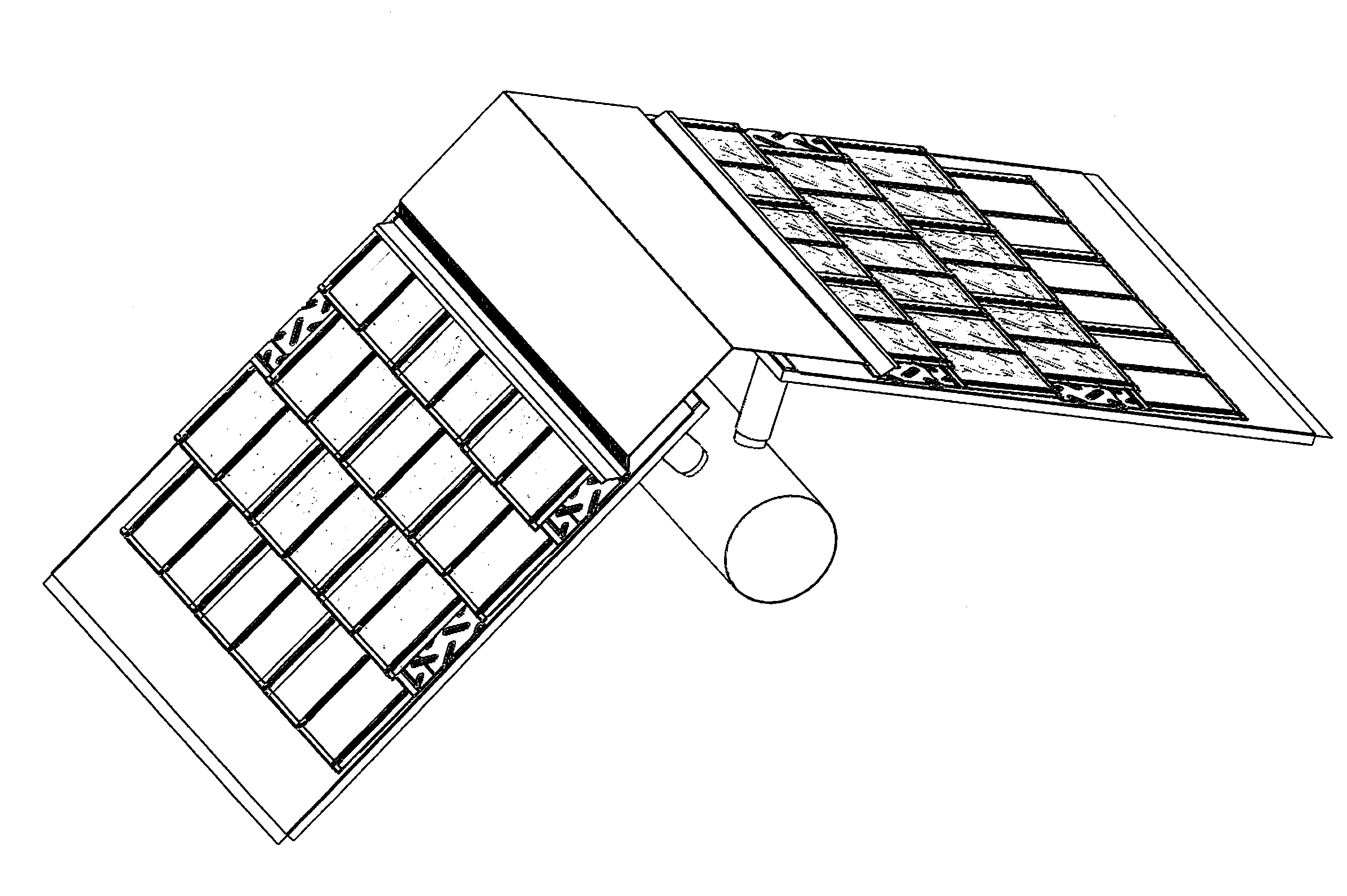
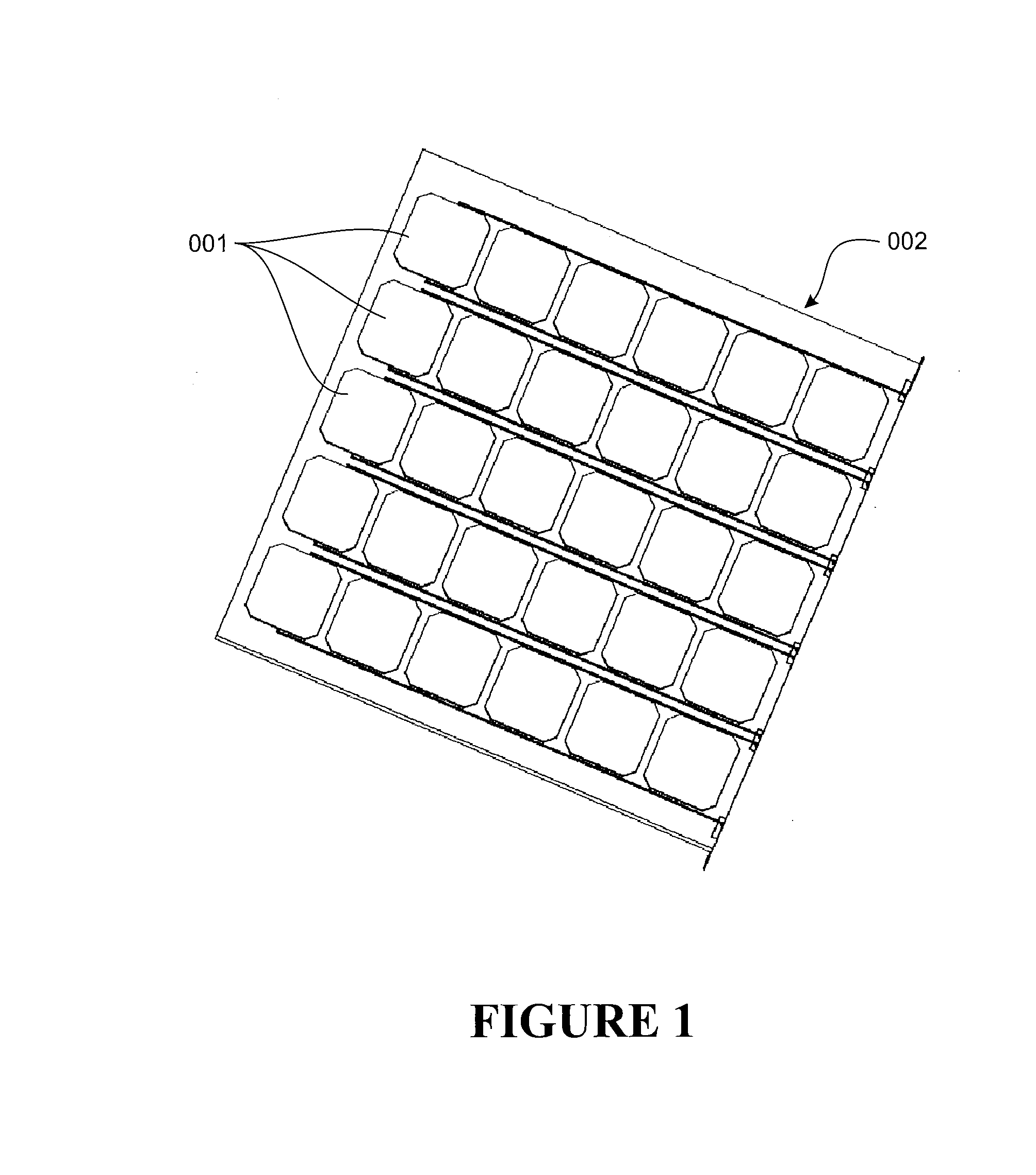
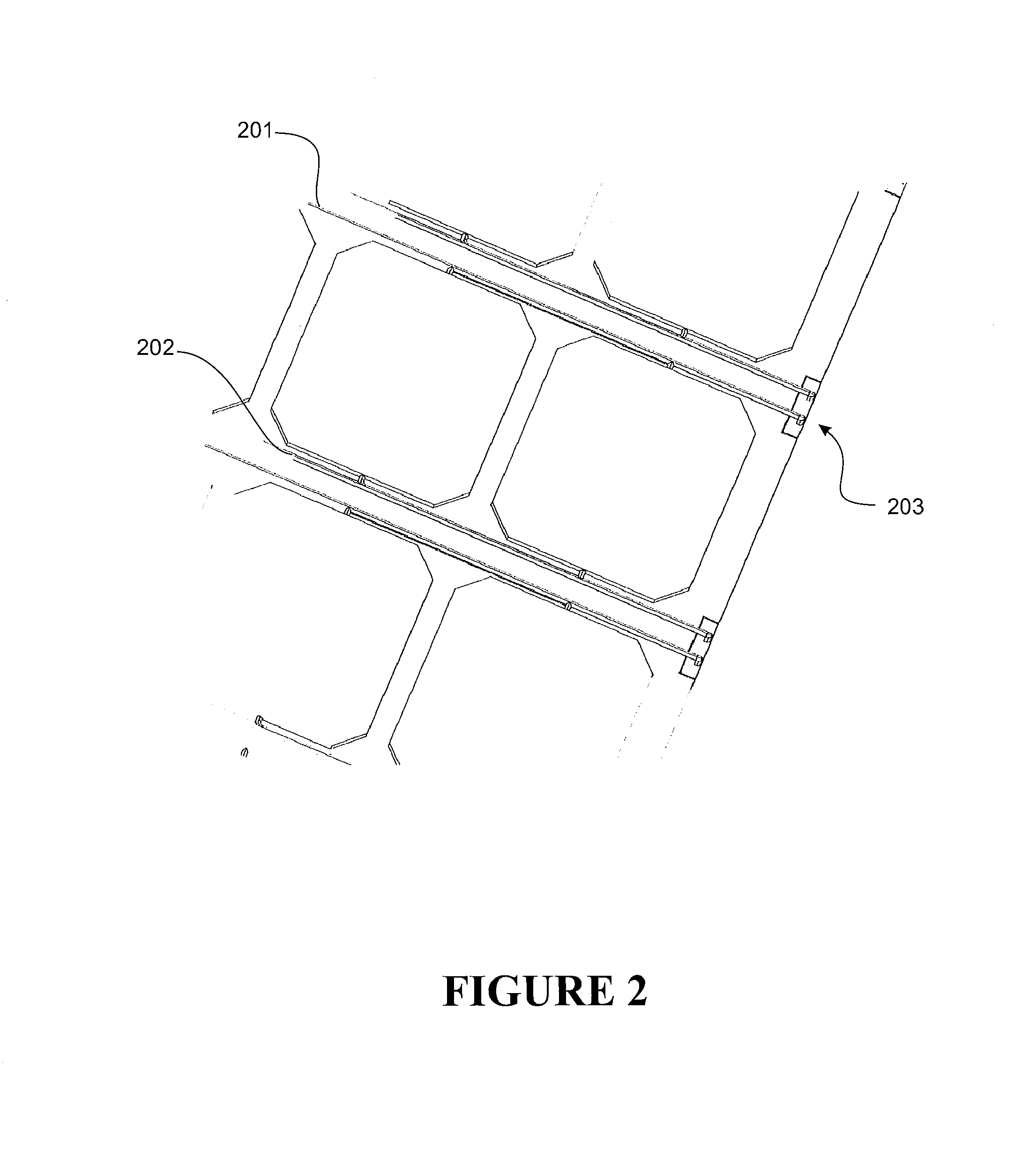
[0305]A first embodiment of the invention is shown in FIG. 1 wherein an array of solar (PV) cells 001 are mounted on a typical glass solar panel 002 and wired in parallel to pairs of positive 201 and negative 202 cables running across the width of the panel (as can been seen more clearly in FIG. 2). Together they form a PV unit and generate electrical / power output (such as output voltage and / or current) at e.g. the right hand end of each cable there is a wireless power transfer (e.g. inductive and / or capacitive) transmission device (transmitter) 203 which may or may not be recessed or encapsulated into the glass. There may be a separate transmission device for each cable, or they may be shared as shown in FIG. 2. The transmitter can transmit power to a reciprocal receiver on a load and / or output conductor.

[0306]For example, a main power take off cable / conductor (which can connect to a load) 301 runs on the underside of the panel in the vertical direction, and there are respective / re...


PUM


Abstract

This invention relates to a roofing panel for interconnection with one or more additional roofing panels. The roofing panel comprises a PV cell coupled to an inverter, and wireless (or optionally wired) power transfer circuitry for transmitting power to another roofing panel and/or the AC grid and/or to an AC inverter, and/or for receiving power from another roofing panel.

Description

FIELD OF THE INVENTION[0001]The present invention relates to photovoltaic (PV) systems and assemblies and their use on roofing products.[0002]More particularly the present invention relates to a method whereby photovoltaic wafers, sails, cells, modules or the like (generally termed “cells”) can be linked or coupled upon installation and / or during installation so as to enable a useful electrical output.BACKGROUND TO THE INVENTION[0003]There are many systems where a substrated PV unit or an unsubstrated PV unit requires an electrical connection to a bus, cable or the like. An instance includes PV electricity generating systems reliant upon an array of PV units whether as standalone arrays or when forming part of, for example, the cladding of a building structure (roof and / or walls).[0004]In many instances the PV unit in whatsoever form it takes (whether stand alone or substrated) is subject to weathering at any electrical connection.[0005]Furthermore, where a plurality of PV units req...

Claims


Application Information

Patent Timeline
IPC IPC(8): H02S20/25H02S40/36H02S40/32
CPCH02S20/25H02S40/36H02S40/32F28F3/044F28F3/048F24S25/61F24S2020/13F24S2025/6008H01L31/048H02S20/26Y02B10/10Y02B10/20Y02E10/47Y02E10/50
Inventor HAYNES, ANDREW LEOPARTRIDGE, ASHTON CYRILBATES, DAVID J.LIU, PENGCHENGTOH, SENG OONNGUANG, SING KIONGSPANOCHE, SORIN
Owner ZINNIATEK
Why Eureka
Try Eureka