
Low Power Asynchronous Counters in a Synchronous System

Active Publication Date: 2016-04-21
AMBIQ MICRO
View PDF3 Cites 6 Cited by
  • Summary
  • Abstract
  • Description
  • Claims
  • Application Information

AI Technical Summary

Benefits of technology

The patent describes an apparatus and method for creating a synchronized clock using an internal clock, an enable signal, and a synchronous clock. The synchronizer facility generates the synchronized clock based on the internal clock, the enable signal, and the synchronous clock. A timer then counts the synchronized clock. The technical effect of this invention is a more precise and accurate means of synchronizing clocks in electronic devices.

Problems solved by technology

Furthermore, it is of no relevance in such systems which specific voltage levels are selected to represent each of the logic states.
However, it is often necessary to read these counters precisely from the processor.
In systems which are focused on low power, there are often two factors which introduce difficulties into the above architecture.
However, the Timer clocks must continue to run even when the system is sleeping, and no clock pulses to the Timer can be added or dropped as the system moves between “sleeping” states where BCLK is not active and “running” states where BCLK is active.
These two requirements make reading the Timer correctly in every situation challenging.
For low frequency timer clocks this is a workable but adds some software complexity.
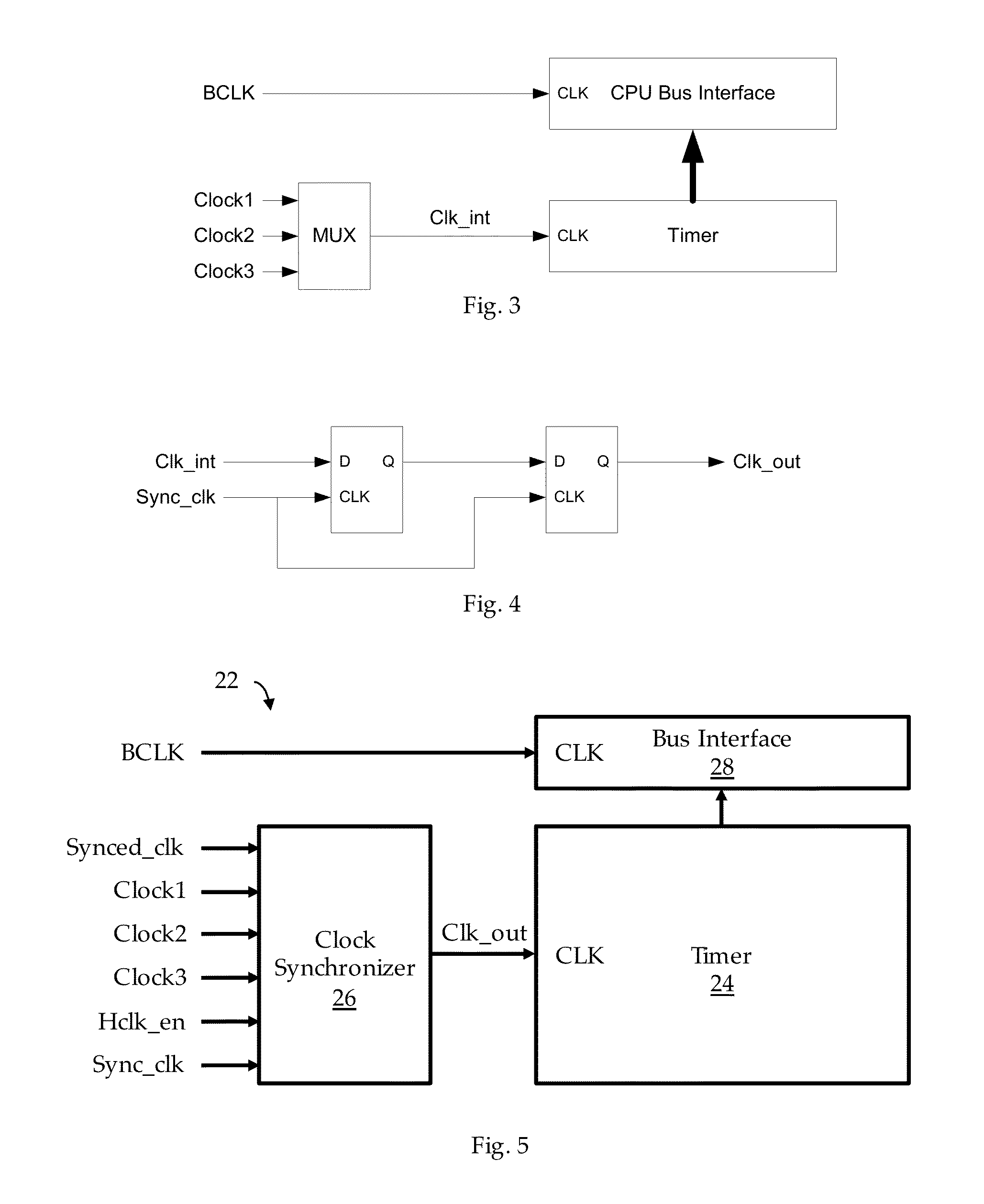
However, the high frequency source oscillator is often a major contributor to system power, and requiring it to remain active at all times can impose a significant power penalty. FIG. 4 illustrates, in block diagram form, a clock synchronization facility.

Method used


Image

  • Low Power Asynchronous Counters in a Synchronous System
  • Low Power Asynchronous Counters in a Synchronous System
  • Low Power Asynchronous Counters in a Synchronous System

Examples


Embodiment Construction

Low Power Method for Precisely Reading an Asynchronous Counter

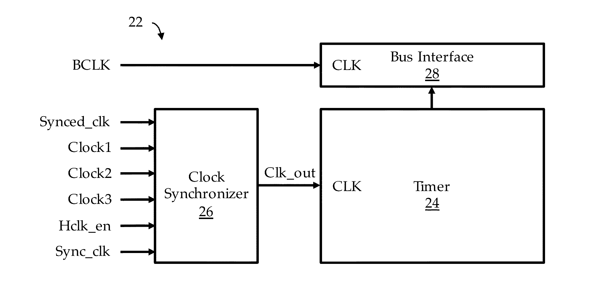
[0047]FIG. 5 illustrates, in block diagram form, a typical integrated timer facility 22 adapted to practice any of the several embodiments. Similar to the earlier discussion, here, the Timer 24 is an N-bit counter which may be loaded with some initial value, and which then counts clock pulses from a selected clock source. And as before, it is desirable that the value in the Timer 24 may be read at any time, even when the Timer 24 is being clocked. The clock synchronizer facility 26 provides the clock synchronizing means for Timer 24 to count and to provide the count data from the Timer 24 to the Bus Interface 28 even when the Timer 24 is being clocked, when Clock1, Clock2, and Clock3 are asynchronous to BCLK, and when BCLK is not active.

[0048]FIG. 6 illustrates, in block diagram form, a clock synchronization facility 26 according to one embodiment. The clock synchronization facility 26 includes mux 28, ASFLOP flip-flop fa...


PUM


Abstract

A clock synchronizer adapted to synchronize reading a Timer that is clocked asynchronously to the system clock.

Description

CROSS REFERENCE TO RELATED APPLICATIONS[0001]This application is related to the following:[0002]1. Provisional Application Ser. No. 62 / 066,218, filed 20 Oct. 2014 (“Parent Provisional”);[0003]2. PCT Application No. PCT / US15 / 50239 filed 15 Sep. 2015 (“Related Application 1”);[0004]3. U.S. application Ser. No. 14 / 855,105, filed 15 Sep. 2015 (“Related Application 2”);[0005]4. U.S. application Ser No. [Docket No. JAM010], filed simultaneously herewith (“Related Application 3”);[0006]5. U.S. application Ser. No. [Docket No. JAM012], file simultaneously herewith (“Related Application 4”); and[0007]6. U.S. application Ser. No. [Docket No. JAM014], filed simultaneously herewith (“Related Application 5”).[0008]This application claims priority to the Parent Provisional, and hereby claims benefit of the filing date thereof pursuant to 37 CFR §1.78(a)(4).[0009]The subject matter of the Parent Provisional and the Related Application, each in its entirety, is expressly incorporated herein by refe...

Claims


Application Information

Patent Timeline
IPC IPC(8): G06F1/12G06F1/10
CPCG06F1/10G06F1/12G06F1/3237G06F1/3287G06F1/06G06F13/102G05F1/56H03K17/687G05F1/575Y02D10/00H03L7/18H03L7/06H03L7/181Y02B70/10H02M1/0045G06F11/3041G06F11/3414G01R19/0084H03M1/12H03L7/00G06F1/3296H02M3/158
Inventor SHEAFOR, STEPHEN JAMES
Owner AMBIQ MICRO
Learn More