MEMS microphone structure and method of manufacturing the same

a microphone and manufacturing method technology, applied in the field of microelectromechanical systems, can solve the problems of exposed upper electrodes being vulnerable to strong releasing solutions and peeling off of the diaphragm

Active Publication Date: 2016-04-21
SHANGHAI INTEGRATED CIRCUIT RES & DEV CENT
View PDF11 Cites 28 Cited by
  • Summary
  • Abstract
  • Description
  • Claims
  • Application Information

AI Technical Summary

Benefits of technology

[0042]The advantage of the present invention is that by using the annular supporter, the releasing process for forming the air gap is stopped inside the annular supporter, such that peeling off of the lower diaphragm electrode due to a too long releasing time can be avoided. Furthermore, the first and second insulating layers completely enclose the upper electrode at the back plate, which provides protection to the upper electrode against damage during the releasing process.

Problems solved by technology

However, such arrangement has the defect that time for releasing the sacrificial dielectric between the diaphragm and the back plate for forming the air gap need to be strictly controlled, since long releasing time may cause completely removal of the sacrificial layer and result in the peel off of the diaphragm.
Furthermore, acoustic holes formed in the back plate communicating with the air gap will expose portion of the upper electrode, which makes the exposed upper electrode vulnerable to strong releasing solution.

Method used


Image

  • MEMS microphone structure and method of manufacturing the same
  • MEMS microphone structure and method of manufacturing the same
  • MEMS microphone structure and method of manufacturing the same

Examples


Embodiment Construction

[0045]Reference will now be made in detail to the present preferred embodiments to provide a further understanding of the invention. The specific embodiments and the accompanying drawings discussed are merely illustrative of specific ways to make and use the invention, and do not limit the scope of the invention or the appended claims.

[0046]Firstly, the MEMS microphone structure of the present invention will be described in detail.

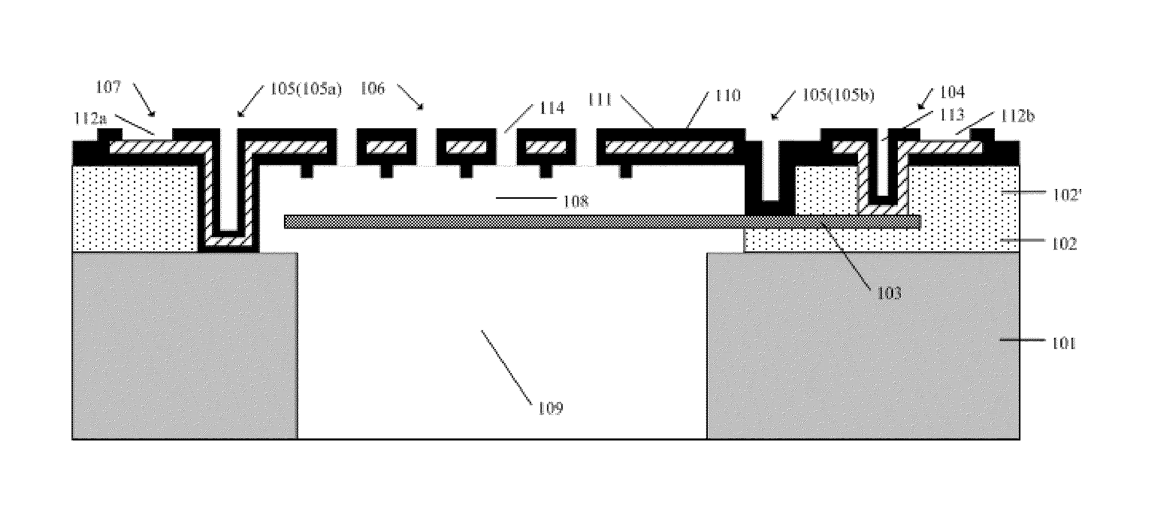
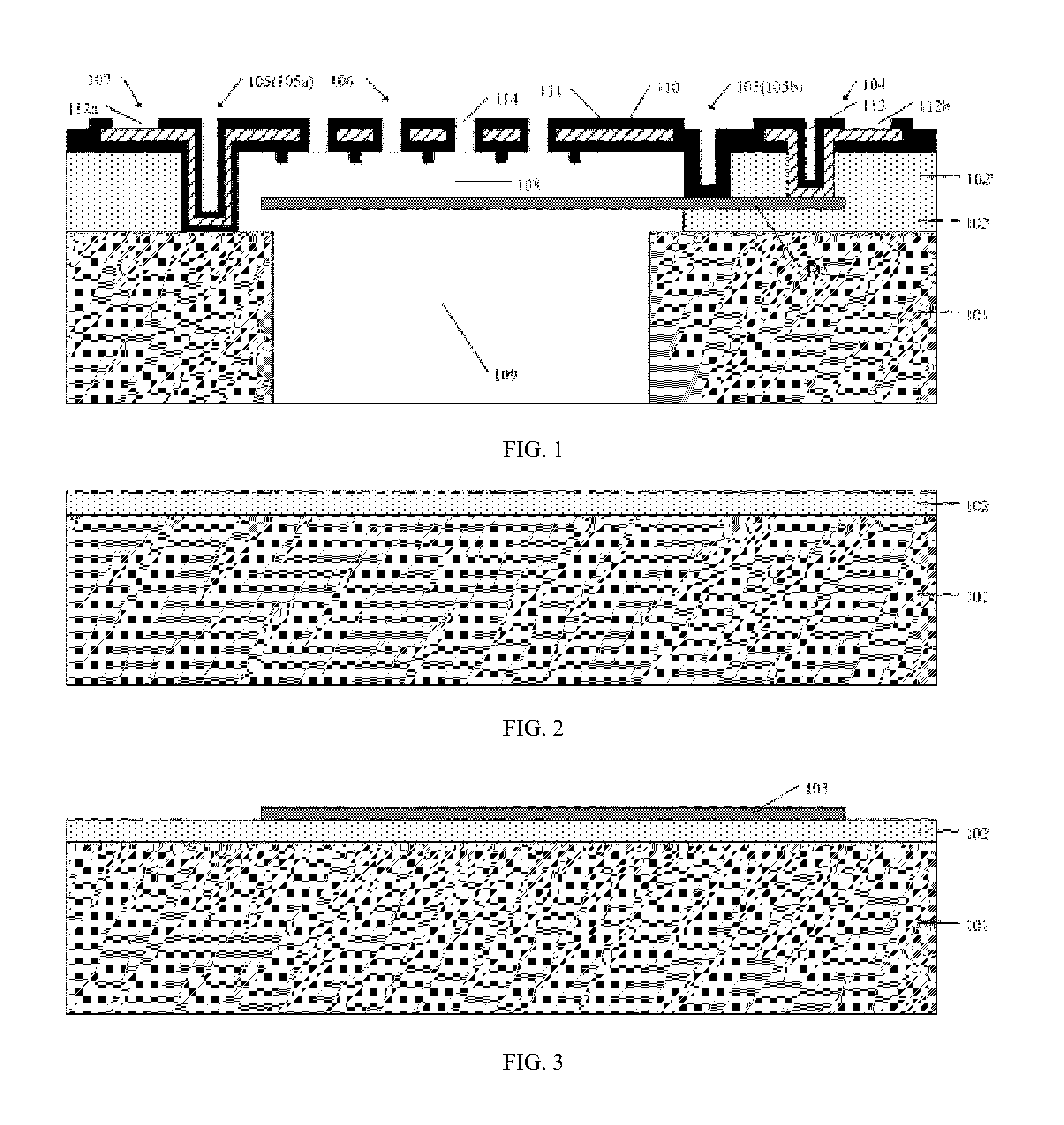
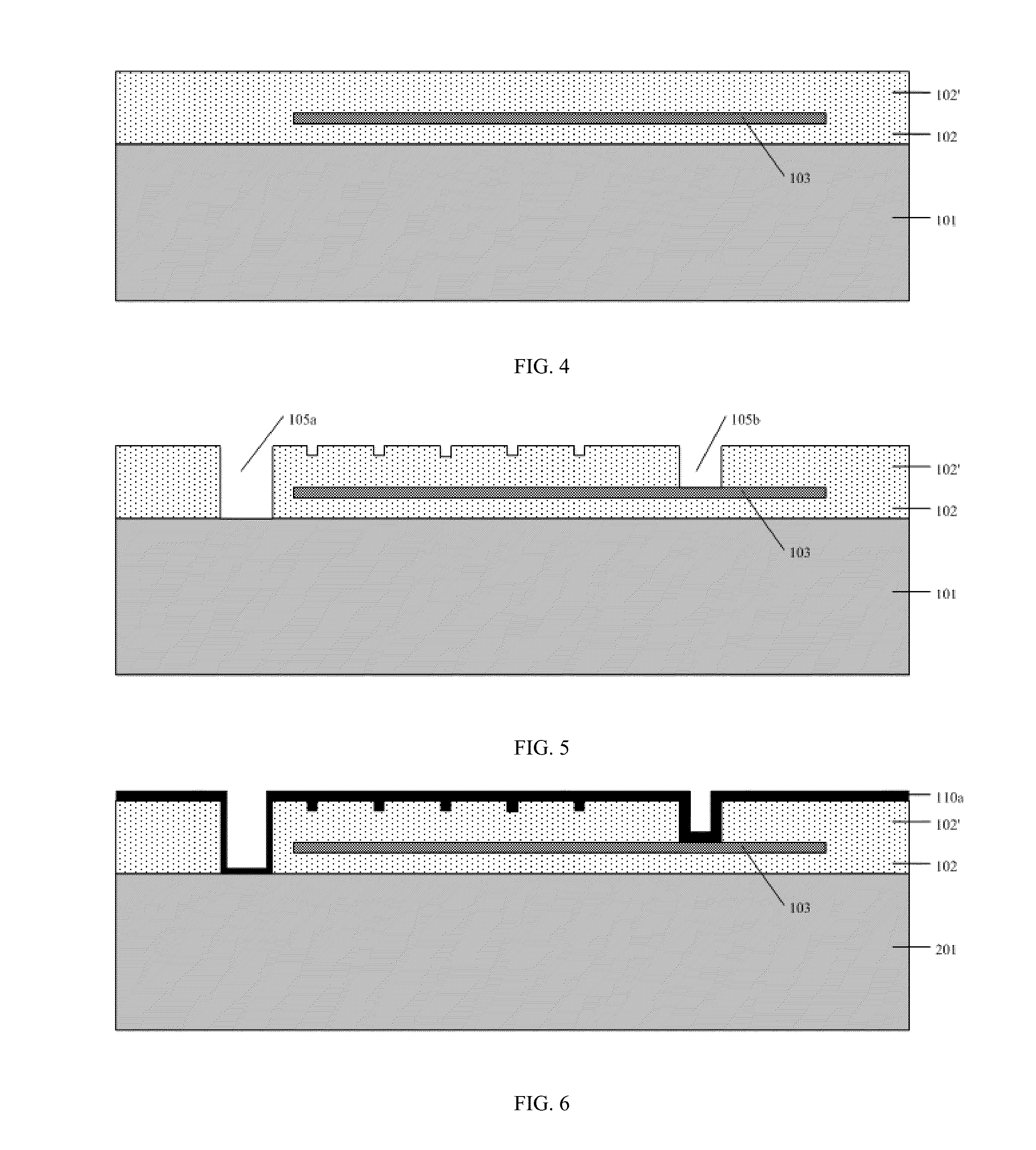
[0047]The MEMS microphone structure comprises a semiconductor substrate, a first dielectric layer, a lower diaphragm electrode, a lower electrode connection and an upper electrode structure. Wherein, a cavity is formed in the substrate by selectively removing part of the semiconductor substrate. The first dielectric layer is formed on the upper surface of the semiconductor substrate, having a through-hole communicating with the cavity. The lower diaphragm electrode is formed above the through-hole and at least partially connected with the upper surface of ...


PUM

PropertyMeasurementUnit
thicknessaaaaaaaaaa
diameteraaaaaaaaaa
thicknessaaaaaaaaaa

Abstract

A MEMS microphone structure, comprising a semiconductor substrate having a cavity, a first dielectric layer having a through-hole communicating with the cavity, a lower diaphragm electrode formed above the through-hole and at least partially attached to the upper surface of the first dielectric layer, and an upper electrode structure with an insulating layer. The upper electrode structure comprises an annular supporter, a back plate having multiple holes, and an upper electrode connection. At least a part of the annular supporter extends downwardly to the lower diaphragm electrode while the rest of the annular supporter extends downwardly to the substrate. The back plate is suspended above the lower diaphragm electrode by the annular supporter, forming an air gap therebetween. An upper electrode is embedded in the insulating layer at the back plate and is lead out by the upper electrode connection.

Description

CROSS-REFERENCE TO RELATED APPLICATION[0001]This application claims the priority benefit of International Patent Application Serial No. PCT / CN2013 / 088,922, filed Dec. 10, 2013, which is related to and claims the priority benefit of China patent application serial No. 201310167692.4 filed May 9, 2013. The entirety of each of the above-mentioned patent applications is hereby incorporated by reference herein and made a part of this specification.FIELD OF THE INVENTION[0002]The present invention generally relates to the field of micro-electro-mechanical-systems, more particularly, to a MEMS microphone structure and a method of manufacturing the same.BACKGROUND OF THE INVENTION[0003]Types of microphones include a dynamic type and a condenser type. The conventional dynamic microphone, which is consisted of a coil, a diaphragm and a permanent magnetic, operates based on the principle that a moving coil in the magnetic field generates electric current. The condenser type microphone, which m...

Claims


Application Information

Patent Timeline
Patent Type & Authority Applications(United States)
IPC IPC(8): H04R19/04H04R31/00B81C1/00H04R19/00
CPCH04R19/04B81C1/00539H04R31/003H04R19/005B81B2201/0257B81C1/00571H04S7/00H04S2420/01
Inventor YUAN, CHAOKANG, XIAOXUZUO, QINGYN
Owner SHANGHAI INTEGRATED CIRCUIT RES & DEV CENT
Why Eureka
Try Eureka