
Atomic magnetometer and operating method of the same

a magnetometer and atomic technology, applied in the field ofatomic magnetometers, can solve the problems of limited sensitivity of magnetic field measurement, limited squid-based sensor wide use, etc., to achieve the effect of expanding the detection bandwidth of vapor

Active Publication Date: 2016-04-28
KOREA RES INST OF STANDARDS & SCI
View PDF4 Cites 115 Cited by
  • Summary
  • Abstract
  • Description
  • Claims
  • Application Information

AI Technical Summary

Benefits of technology

The patent describes an operating method for an atomic magnetometer that uses a feedback coil and a feedback amplifier to extend the detection bandwidth of the magnetometer. This allows for more accurate measurements of the magnet's magnetic properties. Additionally, a negative feedback magnetic field can be used to amplify the output signal of the detector and extend the detection bandwidth of the vapor cell. The technical effects of this method include improved accuracy and sensitivity in measuring magnetic properties, particularly in the case of small changes or magnetic targets.

Problems solved by technology

However, the fluxgate magnetometer is limited in measuring a low magnetic field.
However, the SQUID-based sensor does not come into wide use due to theoretical measurement limitation and costs required for ultra-low temperature cooling for a superconducting phenomenon and required for maintaining the same.
According to the research, it was reported that a limitation of magnetic field measurement sensitivity was 0.6 fT / Hz1 / 2 when Rb atoms were used.

Method used


Image

  • Atomic magnetometer and operating method of the same
  • Atomic magnetometer and operating method of the same
  • Atomic magnetometer and operating method of the same

Examples


Embodiment Construction

[0068]A study on an optical magnetometer using light has been vigorously made as a method for overcoming limitations of SQUIDs. In the field of the optical magnetometer, a study made up to the present time may be roughly summarized in two directions as follows: (1) a method of measuring the degree of refractive index variation of a medium caused by a magnetic field and (2) a method of measuring the degree of shift of a magnetic sublevel. The former is called an optical pumping magnetometer (OPM), and the latter is called a coherent population trapping magnetometer (CPTM).

[0069]The principle of a basic atomic magnetometer is that a Larmor precession frequency of an atomic spin is measured under a magnetic field to measure an external magnetic field.

[0070]Sensitivity of an atomic magnetometer is decided by Iinewidth and nose of a measured signal. There are two ways to improve the sensitivity of an atomic magnetometer.

[0071]One ways is to prevent atoms from colliding against a wall sur...


PUM


Abstract

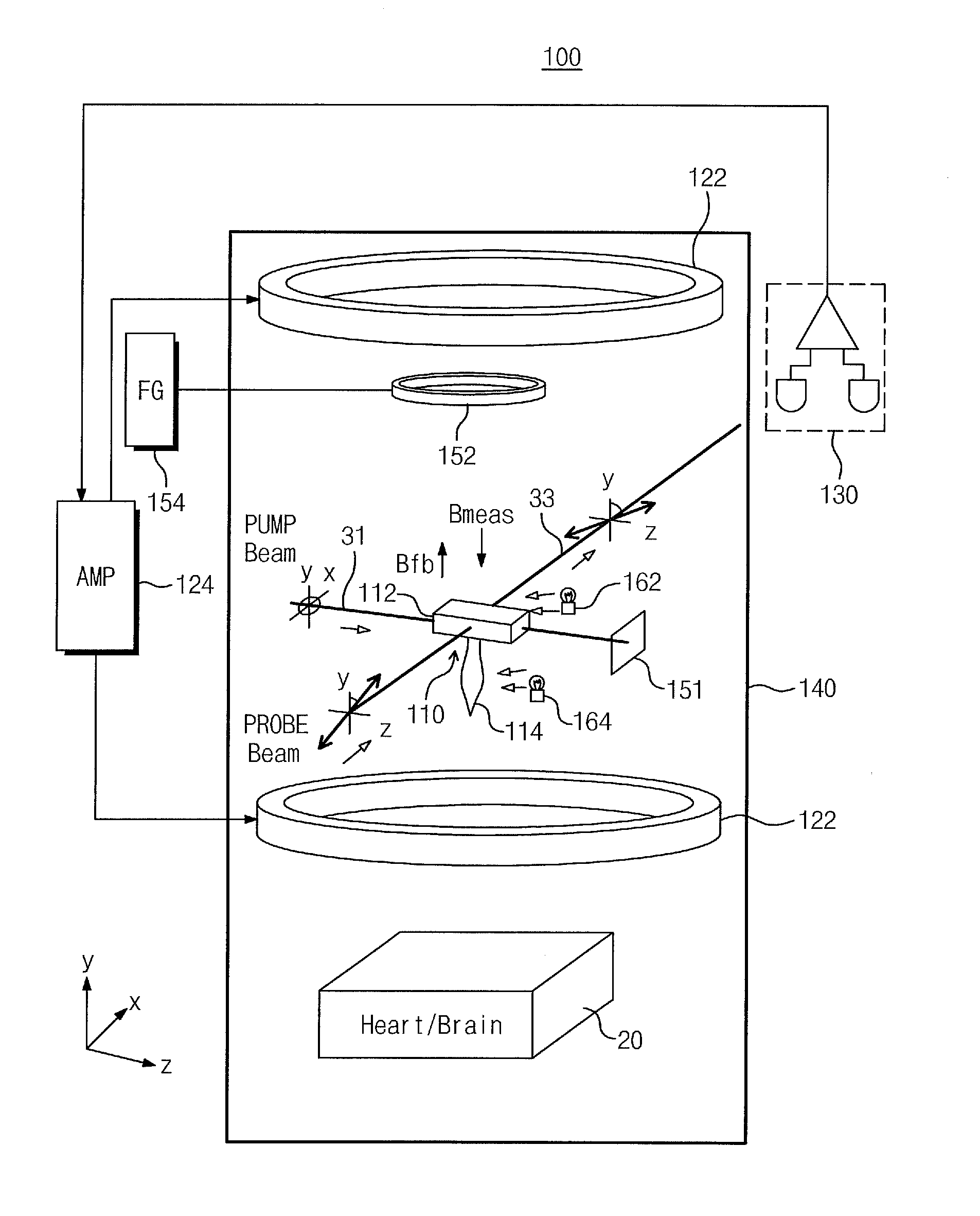
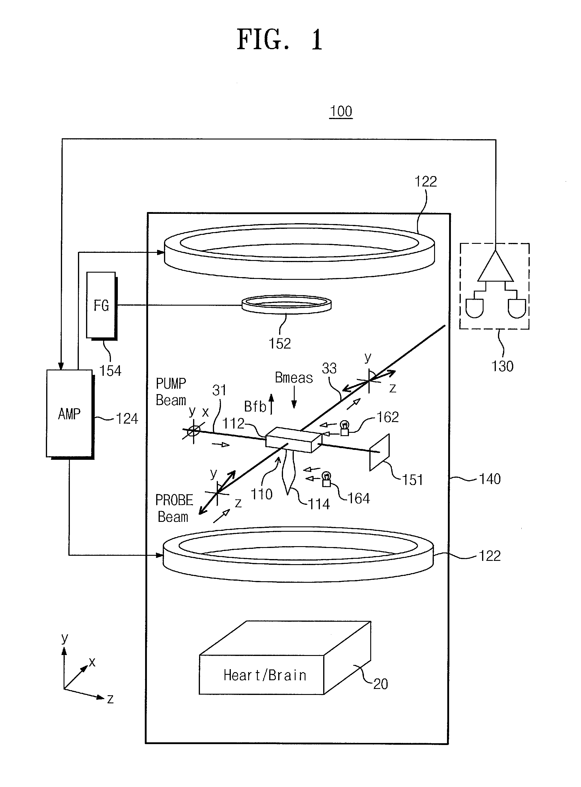
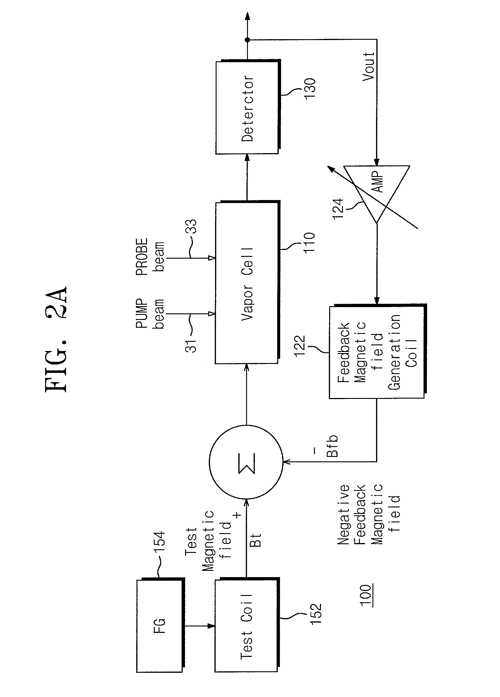
Provided are an atomic magnetometer and an operating method of the same. The atomic magnetometer includes a vapor cell receiving a circularly polarized pump beam and a linearly polarized probe beam and containing an alkali metal vapor, a detector adapted to receive the probe beam passing through the vapor cell to measure magneto-optical rotation of the probe beam, a feedback coil to establish a negative feedback magnetic field signal orthogonal to a first plane defined by traveling directions of the probe beam and the pump beam and provide the negative feedback magnetic field signal to the vapor cell, and a feedback amplifier adapted to provide feedback current to the feedback coil such that the negative feedback magnetic field proportional to a measurement magnetic field is established. The measurement magnetic field of a measurement target provides magneto-optical rotation of the probe beam in the vapor cell.

Description

CROSS-REFERENCE TO RELATED APPLICATION[0001]This U.S. non-provisional application claims priority under 35 U.S.C. §119 to Korea Patent Application No. 10-2014-0145487 filed on Oct. 24, 2014, the entirety of which is hereby incorporated by reference.BACKGROUND[0002]1. Field of the Invention[0003]The present invention generally relates to atomic magnetometers and, more particularly, atomic magnetometers having negative feedback.[0004]2. Description of the Related Art[0005]In the ubiquitous health (U-Health) age pursuing safety life and healthy life that are the trends of 21 century, development and measurement / analysis techniques of a biomagnetic measurement apparatus, such as magnetocardiography (hereinafter referred to as “MCG”) and magnetoencephalography (hereinafter referred to as “MEG”), based on a technique of an optical-pumping atomic magnetometer that is an ultra-sensitive magnetic sensor (magnetometer) are core techniques for the next-generation ultra-sensitive instant diagno...

Claims


Application Information

Patent Timeline
Patent Type & Authority Applications(United States)
IPC IPC(8): G01R33/26G01R33/032
CPCG01R33/032G01R33/26G01R33/00G01R33/02
Inventor KIM, KIWOONGLEE, HYUN-JOONSHIM, JEONG-HYUN
Owner KOREA RES INST OF STANDARDS & SCI
Learn More