Transcatheter valve prosthesis having an external skirt for sealing and preventing paravalvular leakage

a transcatheter valve and prosthesis technology, applied in the field of transcatheter valve prosthesis, can solve the problems of valve not opening properly, insufficiency or regurgitation, stenosis and insufficiency, etc., and achieve the effect of low profil

Active Publication Date: 2016-05-05
MEDTRONIC VASCULAR INC
View PDF3 Cites 47 Cited by
  • Summary
  • Abstract
  • Description
  • Claims
  • Application Information

AI Technical Summary

Benefits of technology

[0006]Embodiments hereof relate to a transcatheter valve prosthesis including a tubular stent having a compressed configuration for delivery within a vasculature and an expanded configuration for deployment within a native heart valve. The tubular stent includes a plurality of crowns and a plurality of struts with each crown being formed between a pair of opposing struts, the tubular stent having endmost crowns formed at an inflow end thereof. A skirt is coupled to the tubular stent, with a first portion of the skirt being attached to and covering an inner circumferential surface of the tubular stent and a second portion of the skirt being attached to and covering an outer circumferential surface of an inflow end of the tubular stent. The skirt is continuous from the first portion to the second portion such that the first and second portions do not overlap. A prosthetic valve component is disposed within and secured to the first portion of the skirt. When the tubular stent is in at least the compressed configuration at least one endmost crown is positioned radially inwards with respect to the remaining endmost crowns formed at the inflow end of the tubular stent.
[0007]According to another embodiment hereof, a transcatheter valve prosthesis includes a tubular stent having a compressed configuration for delivery within a vasculature and an expanded configuration for deployment within a native heart valve. The tubular stent includes a plurality of crowns and a plurality of struts with each crown being formed between a pair of opposing struts. The plurality of crowns and the plurality of struts define a plurality of openings of the tubular stent and the tubular stent has endmost crowns and endmost openings formed at an inflow end thereof. An interior skirt is coupled to and covers an inner circumferential surface of the tubular stent. A prosthetic valve component is disposed within and secured to the interior skirt. An exterior skirt is coupled to and covers an outer circumferential surface of the tubular stent. The exterior skirt longitudinally extends over at least the endmost openings of the tubular stent. When the tubular stent is in at least the compressed configuration at least one endmost crown is positioned radially inwards with respect to the remaining endmost crowns formed at the inflow end of the tubular stent, thereby forming a circumferentially-extending gap between the endmost crowns adjacent to the at least one endmost crown positioned radially inwards in order to provide a low profile while accommodating the exterior skirt.
[0008]According to another embodiment hereof, a transcatheter valve prosthesis includes a tubular stent having a compressed configuration for delivery within a vasculature and an expanded configuration for deployment within a native heart valve. A skirt is coupled to the tubular stent, with a first portion of the skirt being attached to and covering an inner circumferential surface of the tubular stent and a second portion of the skirt being attached to and covering an outer circumferential surface of an inflow end of the tubular stent. The skirt is continuous from the first portion to the second portion such that the first and second portions do not overlap. A prosthetic valve component is disposed within and secured to the first portion of the skirt.

Problems solved by technology

Problems that may develop with valves include stenosis in which a valve does not open properly, and / or insufficiency or regurgitation in which a valve does not close properly.
Stenosis and insufficiency may occur concomitantly in the same valve.
The effects of valvular dysfunction vary, with regurgitation or backflow typically having relatively severe physiological consequences to the patient.
Although transcatheter delivery methods may provide safer and less invasive methods for replacing a defective native heart valve, leakage between the implanted prosthetic valve and the surrounding native tissue may occur if not accommodated for by a particular implant.
For instance, leakage may occur due to the fact that deployment of a minimally invasive cardiac valve is intended to occur without actual physical removal of the diseased or injured heart valve.
However, it has been shown that calcified leaflets do not allow complete conformance of a stent frame with a native valve and therefore this ill-fit within the native anatomy may be a source of paravalvular leakage (PVL), as significant pressure gradients across the implanted prosthetic valve may cause blood to leak through the gaps between the implanted prosthetic valve and the calcified anatomy.

Method used


Image

  • Transcatheter valve prosthesis having an external skirt for sealing and preventing paravalvular leakage
  • Transcatheter valve prosthesis having an external skirt for sealing and preventing paravalvular leakage
  • Transcatheter valve prosthesis having an external skirt for sealing and preventing paravalvular leakage

Examples


Embodiment Construction

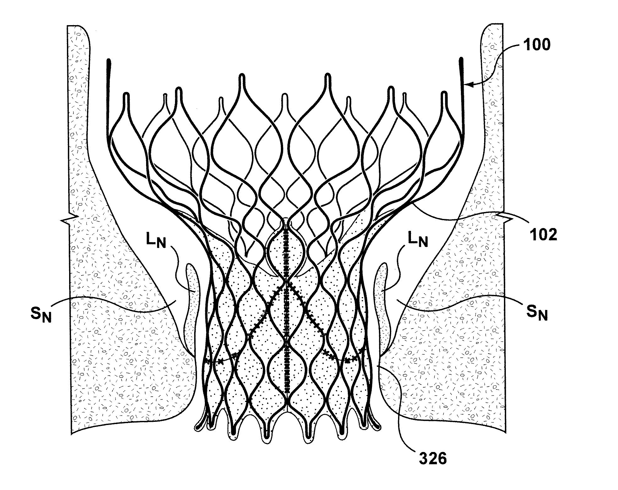
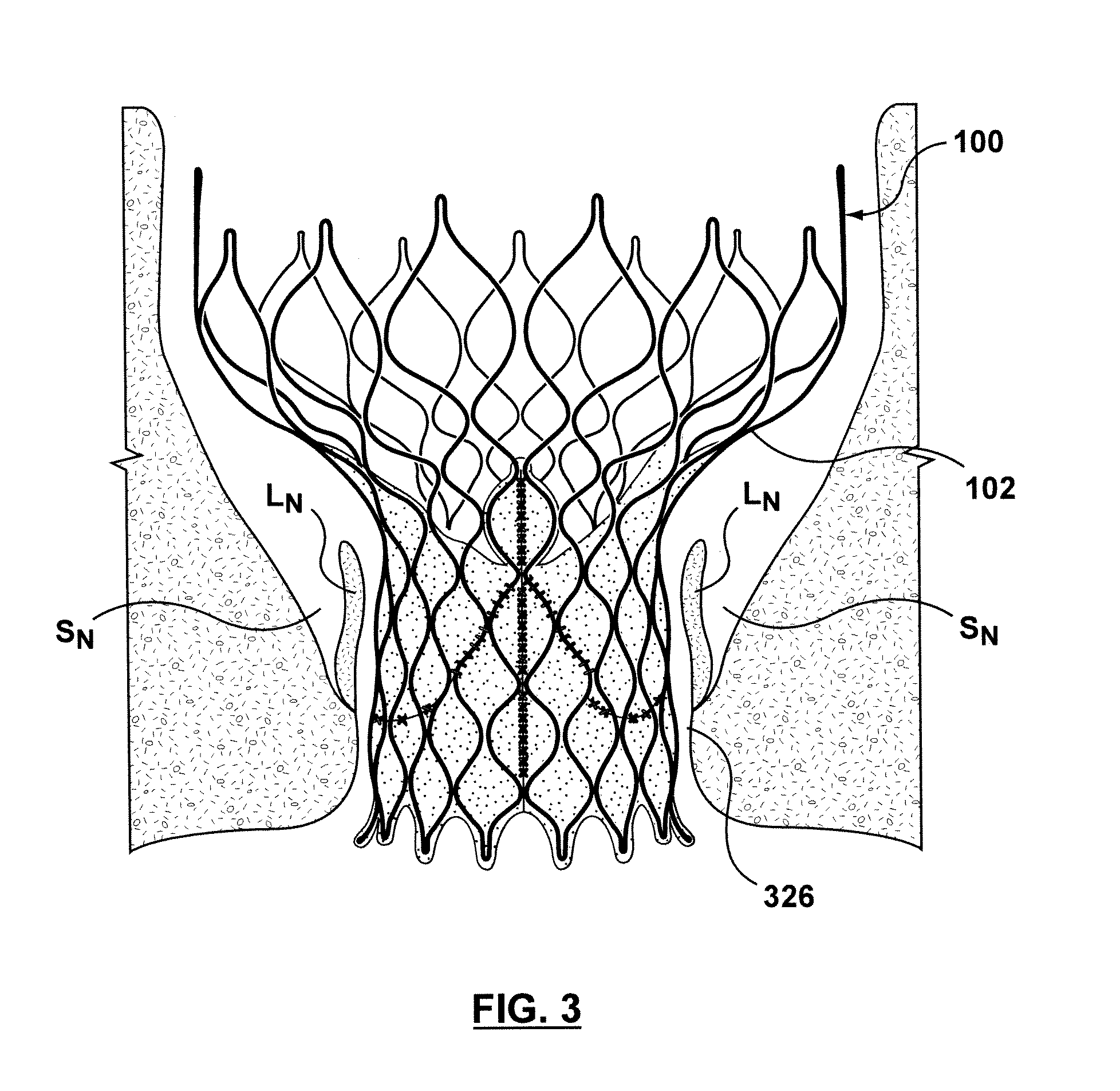
[0026]Specific embodiments of the present invention are now described with reference to the figures, wherein like reference numbers indicate identical or functionally similar elements. If utilized herein, the terms “distal” or “distally” refer to a position or in a direction away from the heart and the terms “proximal” and “proximally” refer to a position near or in a direction toward the heart. The following detailed description is merely exemplary in nature and is not intended to limit the invention or the application and uses of the invention. Although the description of the invention is in the context of treatment of heart valves, the invention may also be used where it is deemed useful in other valved intraluminal sites that are not in the heart. For example, the present invention may be applied to venous valves as well. Furthermore, there is no intention to be bound by any expressed or implied theory presented in the preceding technical field, background, brief summary or the ...


PUM


Abstract

A transcatheter valve prosthesis including a tubular stent includes an interior skirt or skirt portion is coupled to and covers an inner circumferential surface of the stent, and an exterior skirt or skirt portion is coupled to and covers an outer circumferential surface of the stent. A prosthetic valve component is disposed within and secured to the interior skirt or skirt portion. The interior and exterior skirts or skirt portions may overlap to form a double layer of skirt material on the stent, or may be portions of a skirt that do not overlap such that only a single layer of skirt material covers the stent. When the stent is in at least the compressed configuration, at least one endmost crown may be positioned radially inwards with respect to the remaining endmost crowns formed at the inflow end of the stent in order to accommodate the exterior skirt.

Description

FIELD OF THE INVENTION[0001]The present invention relates in general to transcatheter valve prostheses, and more particularly to a transcatheter valve prosthesis having one or more components for preventing paravalvular leakage.BACKGROUND OF THE INVENTION[0002]A human heart includes four heart valves that determine the pathway of blood flow through the heart: the mitral valve, the tricuspid valve, the aortic valve, and the pulmonary valve. The mitral and tricuspid valves are atrioventricular valves, which are between the atria and the ventricles, while the aortic and pulmonary valves are semilunar valves, which are in the arteries leaving the heart. Ideally, native leaflets of a heart valve move apart from each other when the valve is in an open position, and meet or “coapt” when the valve is in a closed position. Problems that may develop with valves include stenosis in which a valve does not open properly, and / or insufficiency or regurgitation in which a valve does not close prope...

Claims


Application Information

Patent Timeline
Patent Type & Authority Applications(United States)
IPC IPC(8): A61F2/24
CPCA61F2210/00A61F2/2469A61F2/2412A61F2/2418A61F2230/008A61F2220/0075A61F2250/0069
Inventor DWORK, JOSHUAMOSHER, SCOTT
Owner MEDTRONIC VASCULAR INC
Why Eureka
Try Eureka