Minimally invasive approaches, methods and apparatuses to accomplish sacroiliac fusion

a sacroiliac joint, minimally invasive technology, applied in the field of medical procedures, can solve the problems of no surgical intervention that is adequately and securely fused, and the pain associated with the si joint is common

Inactive Publication Date: 2016-05-05
MIS IP HLDG LLC
View PDF7 Cites 49 Cited by
  • Summary
  • Abstract
  • Description
  • Claims
  • Application Information

AI Technical Summary

Problems solved by technology

Pain associated with the SI joint commonly occurs from increased unwanted movement of the joint that increases movement of the sacrum and / or ilium.
According to a study administrating a series of standardized questionnaires to patients undergoing SI joint treatment, sacroilitis contributes to a significant burden on the health status of a patient.
However, no surgical intervention adequately and securely fuses the SI joint without problems associated with prior art procedures, such problems including a substantial level of trauma, pain and a long recovery time.
Many traditional methods and procedures associated with SI joint fusion require open, non-minimally invasive procedures, often causing an elevated level of trauma, greater pain and a longer recovery time for the subjects of such methods and procedures.
The reliance upon a single screw to secure the SI joint, as associated with several prior art procedures, is often insufficient to effectively stabilize the SI joint.
Although a plurality of anchoring implants have also been used within the SI joint area, as disclosed in U.S. Pat. No. 8,734,462 and elsewhere, the weight and movement forces that the various anatomical structures related to and near the hip area must face can potentially lead to a loosening of the screws and / or anchoring implants associated with such prior art surgeries.
Often, the failure of a SI fusion results from the utilization of previously known methods where devices placed in association with such methods will break.
Such breakage occurs because of the excessive forces associated with the sacral iliac joint and anatomical structures located near the hip area.
Previously known methods fail to adequately and effectively address these forces.
Because of the excessive forces the SI joint experiences, inadequate SI joint fusions deriving from previously known methods can lead to a variety of problems.
After a typical previously known surgical procedure intended to address problems associated with the SI joint, mechanical stress on the bone surrounding the SI joint and anchoring implants placed during such procedure may further degrade the bone surrounding the anchoring implants, leading to pseudoarthrosis, costly and risky return surgery, complications, and failed clinical outcome.
Such problems also include without limitation the failure of associated instrumentation, the breakage of associated instrumentation, and continued undesirable motion of the SI joint.
However, in some cases, the SI joint space may not be sufficiently accessible to accommodate such an implant given the anatomical structure of a patient.
However, many previously known methods and procedures related to the SI joint fail to take advantage of such recent developments in technology.
Such methods and procedures often fail to effectively and adequately accomplish bony fusion using allograft, auto graft or structural implants within the joint space.
Some prior art procedures and methods fail to effectively incorporate the use of bone or bone substitutes placed deep within the joint, and thereby often result in suboptimal bone fusion, breakage of instrumentation and pseudoarthrosis.
Some methods and procedures involve the placement of bone grating through or in the region of the sacral iliac joint, however a related problem is that the placement of the bone generally does not take place deep into the joint.
As a result, poor sacral iliac fusions thereby result from the suboptimal placement of bone.
Yet, in such prior art, the problem of potential movement between the sacrum and ilium after the surgery remains unsolved.
Such previously known methods and apparatuses fail to take advantage of the benefits associated with the cleaning and decortication of the articular surfaces and the addition of bone graft materials within the joint space.
A previously unsolved problem therefore is a failure to effectively combine the use of biological grafts within the SI joint with mechanical compression of such joint.
Further, some previously known methods and procedures associated with the SI joint lack the percutaneous placement of screws, where open placement of screws is more common.
The trauma associated with open placement of screws associated with prior art procedures causes an elevated risk of nerve, abdominal, and vascular injuries, excessive tissue trauma, hematomas, and infections of soft tissues.
Additionally, some of the more recent techniques do not allow for the direct visualization of the bony joint surface, which is considered a preferred method of surgery in some cases and often a requirement mandated by insurance companies to receive reimbursement for fusion procedures.
Moreover, there is a risk that prior art procedures and methods leading to a high incidence of pseudoarthrosis, instrumentation failure, and poor clinical outcomes.
While improvements have been made in decreasing the invasiveness of the minimally invasive SI joint surgeries, previously known techniques and methods associated with minimally invasive SI joint surgeries still pose a significant risk for complications.
For example, depending on the site of the incision, the chance of hematoma (collection of blood outside of blood vessels) and / or infection increases with the size of the surgical incision.
Therefore, such incisions and associated instrumentation related to previously known minimally invasive SI joint procedures have a significant potential to cause damage to tissue, nerves, and bone structures.
These also lead to a substantial risk of hematoma and / or infections during and after surgery.
Furthermore, by creating a larger incision site, the larger incision site becomes more problematic in cases where the entry site for the corresponding implant needs to be changed during the surgery.
This additional discomfort and / or pain may occur because of the imbalance of the stabilization when only one SI joint is secured.
The process of securing both the left and right SI joints, has been previously reported to be ineffective.
Furthermore, the Dorsal Bilateral Interlocking Technique and other prior art procedures are generally invasive and require a large surgical wound (typically a 10 to 15 cm incision) of the posterior region of the body, wherein the large surgical wound has significant potential to cause damage to tissue, muscle, nerves, and bone structures, and access to the appropriate spinal structures to achieve fusion further requires temporary displacement and / or removal of tissue, muscle, nerves, and other bodily structures.
An obvious side-effect to these invasive procedures is that they have substantial risk of causing hematoma and / or infections during and after surgery due to the large size and great impact to the surgical site.

Method used


Image

  • Minimally invasive approaches, methods and apparatuses to accomplish sacroiliac fusion
  • Minimally invasive approaches, methods and apparatuses to accomplish sacroiliac fusion
  • Minimally invasive approaches, methods and apparatuses to accomplish sacroiliac fusion

Examples


example 1

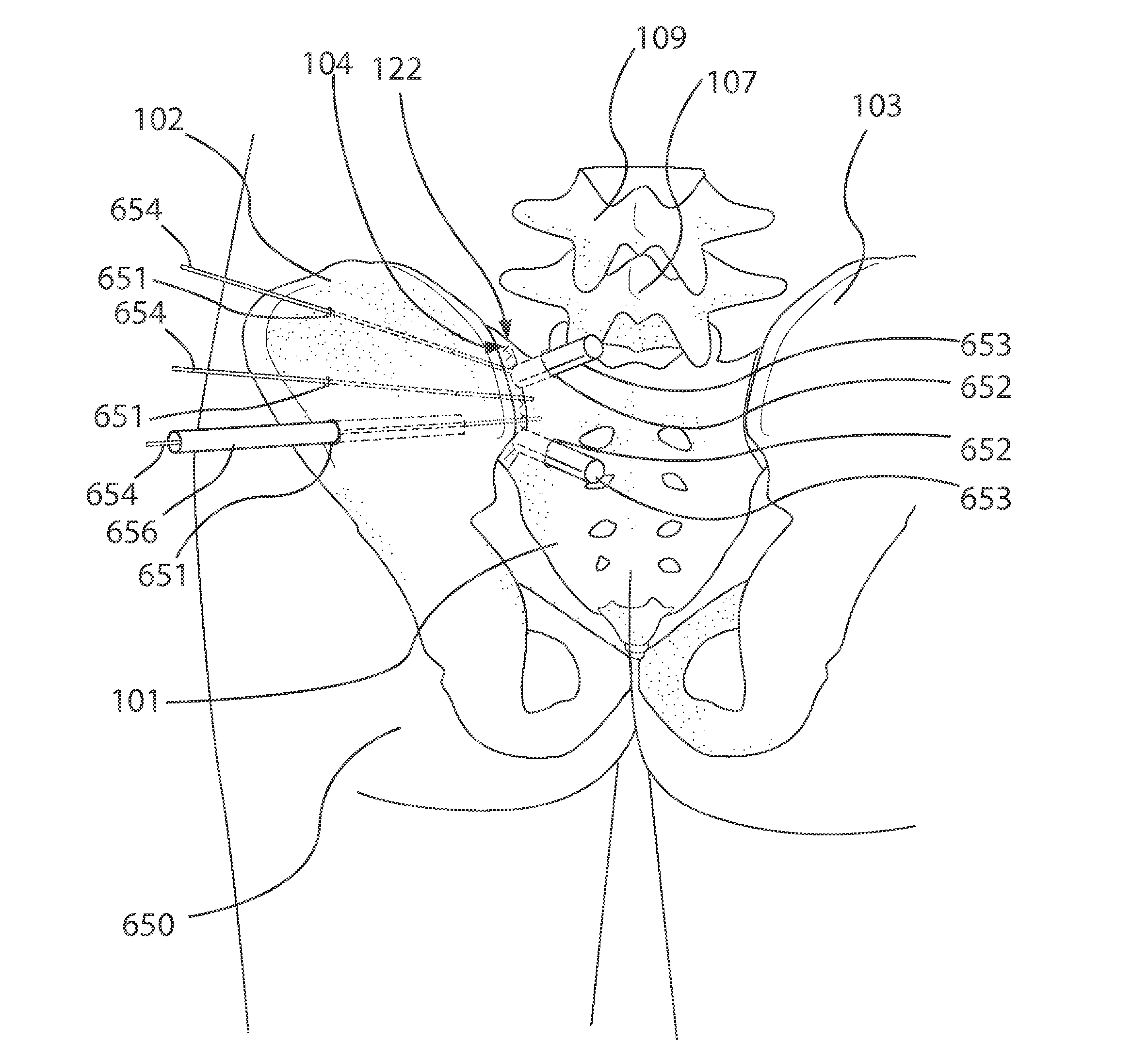
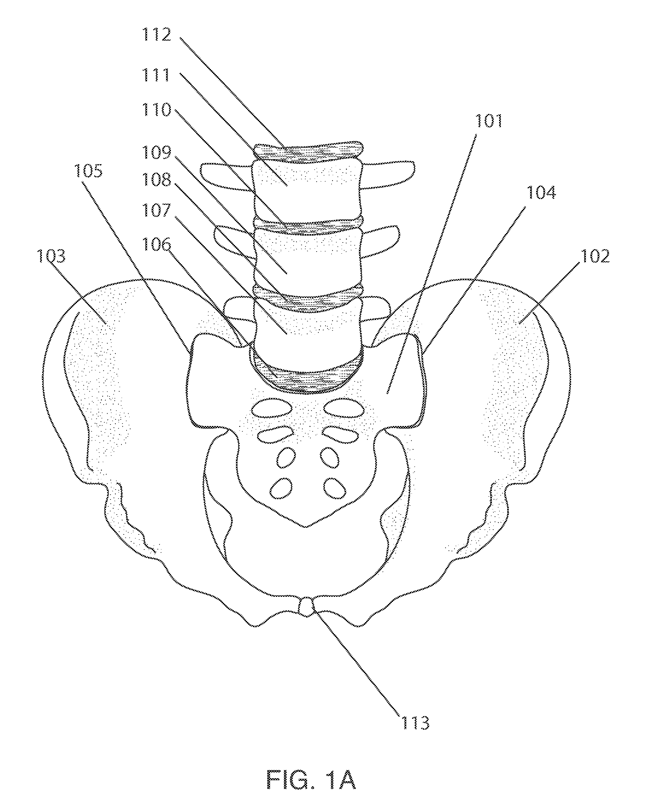
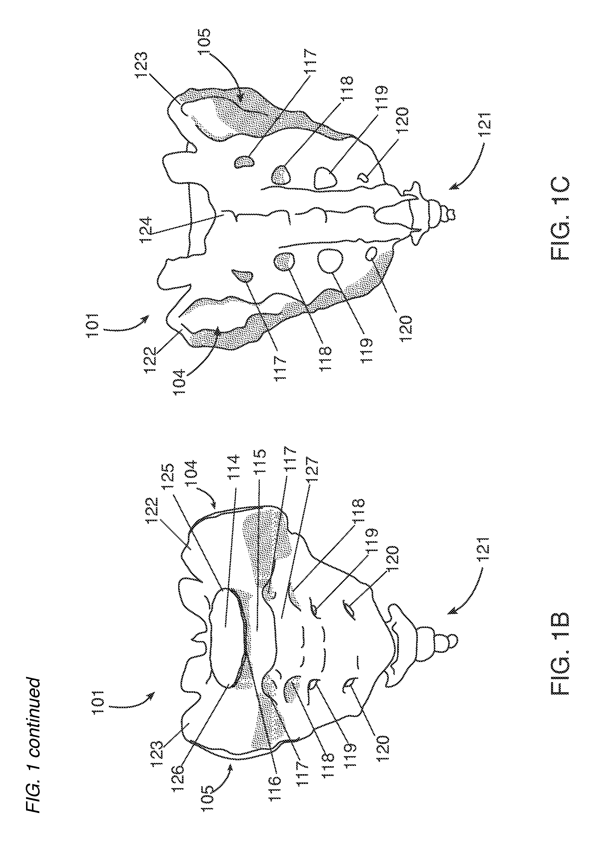
[0261]During the secure SI joint with bilateral device step 255, a medical practitioner inserts a bilateral device into the bilateral device path 702, as to secure a left ilium 102, the right ilium 103, and the sacrum 101, and further compressing the left SI joint 104 and the right SI joint 105 as to minimize pain associated with sacroilitis and other afflictions related to a loosened SI joint or SI joints. In certain embodiments, a bilateral device compresses a left ilium, right ilium, and sacrum to ensure that both ilia are secured simultaneously. In certain embodiments of the invention, stabilizer devices further secure individual ilia to the respective side of a sacrum.

[0262]An embodiment of a bilateral device is shown in FIG. 23A, where the bilateral device 2301 further comprises two components. In certain embodiments, a first component 2301a joins with a second component 2301b. In one embodiment of the invention, the first component 2301a is secured to second component 2301b w...

example 2

[0264]In certain embodiments, a bilateral device may have an oblong component that traverses the sacrum. In certain embodiments, a bilateral device may have an oblong component having a feature at one end. In one example, a bilateral device 2500 comprises a component 2502 or 2516, a floating screw 2501, and an end screw 2509, as shown in examples FIG. 25A, FIG. 25B, FIG. 25E, FIG. 25G, and FIG. 2511. In certain embodiments, a component 2502 further has a threaded head 2506 and a shaft 2507, as shown in the example in FIG. 25B. Certain embodiments of an end screw 2509, as shown in the example in FIG. 25E, fastens a floating screw 2501 to a female thread 2505 located on one end of a component 2502, 2516, as shown in an example in FIG. 25C, FIG. 25D, and FIG. 25G. A floating screw 2501, as shown in FIG. 25F, may also have drive 2514 that can allow axial rotation of such screw 2501 with a driver as well as accommodating a diameter of an end screw head 2512, and further have an smaller d...

example 3

[0268]In certain embodiments, a bilateral device comprises an oblong component, which can have features fastened, attached, threaded, fitted, on both sides of such component. In certain embodiments, a bilateral device 2520 comprises a component 2521 having an oblong shape, as shown in an example in FIG. 6A, FIG. 26B, further having threads 2523 (shown for example in FIG. 25D) on both ends. In certain embodiments a shaft region, for example, shaft 2527 (also, for example, on component 2541) comprises a spline 2524 running in a longitudinal direction, as shown in for example, FIG. 26C. A plurality of splines 2524 may be arranged circumferentially along such shaft, forming one or more grooves 2525, as shown in example FIG. 26C, FIG. 30C. Certain embodiments of a component has an axial opening 2526 or 2574, as shown in example FIG. 26C or FIG. 31G, that allows a medical practitioner to slide a component over, for example, a guide wire.

[0269]In certain embodiments, a wedge end screw 2522...


PUM


Abstract

The present disclosure presents novel methods, procedures associated steps, and apparatuses to accomplish SI joint fusion in a minimally invasive manner. The preferred embodiment of the invention incorporates improved methods, procedures and apparatuses to facilitate a SI joint fusion providing a generally safer, more minimally invasive SI joint stabilization. In the method associated with the preferred embodiment of the invention, in one aspect, a path or a plurality of paths through an ilium to the sacrum is established, wherein a stabilizer device allows the securement of the sacrum to the ilium. In another aspect, a path or a plurality of paths to the SI joint is established, where bone fusion material allows fusion of the articular surface of the ilium and the articular surface of the sacrum of an SI joint.

Description

CROSS REFERENCE TO RELATED APPLICATIONS[0001]The present application claims the benefit of U.S. provisional application 62 / 068,602, filed Oct. 24, 2014, and provisional application 62 / 105,045, filed Jan. 19, 2015. The entire disclosures of the above references are incorporated herein by reference in entirety for all purposes.FIELD OF THE INVENTION[0002]The field relates generally to a medical procedure, and more particularly to a medical process of the sacroiliac joint.BACKGROUND[0003]Problems associated with the weakening and inflammation of the sacroiliac joint, or “SI joint,” are among the most prevalent causes of lower-back pain. Sacroilitis, or sacroiliac joint dysfunction, is inflammation of one or both SI joints that can lead to extensive pain in the lower back region. Causes of sacroilitis include trauma of the lower back from injury, osteoarthritis of the spine, and infection of the SI joint. Additionally, childbirth is a common causative event for sacroilitis, as pelvic wi...

Claims


Application Information

Patent Timeline
Patent Type & Authority Applications(United States)
IPC IPC(8): A61F2/46A61F2/30A61B17/70
CPCA61F2/4601A61B17/7055A61F2002/4635A61F2002/30995A61F2/30988A61B17/1671A61B17/8605A61B17/863A61B17/8685A61B17/8695
Inventor SCHELL, GERALD R.SCHELL, JEFFREY R.EYVAZZADEH, DAVID C.OKKOTSU, YUTA
Owner MIS IP HLDG LLC
Why Eureka
Try Eureka