Flying object operating system

a flying object and operating system technology, applied in the field of flying objects, can solve the problems of insufficient buoyancy of the airship, the solution to solve this problem entails a huge cost, and the difficulty of electric power supply through such a connection to the ground, so as to achieve the effect of less power, more buoyancy, and energy efficiency during the operation of flying objects

Inactive Publication Date: 2016-05-05
JANG SOO YOUNG
View PDF1 Cites 11 Cited by
  • Summary
  • Abstract
  • Description
  • Claims
  • Application Information

AI Technical Summary

Benefits of technology

[0059]As mentioned above, the flying object operating system according to the present invention may have the following effects.
[0060]In other words, the present invention provides a flying object operating system which equips with a self-position detection function and a position control function, whereupon a flying object designed to perform a given mission at a fixed position can obtain stability when carrying out a corresponding mission.
[0061]In addition, in the present invention, since a position control of a flying object can be carried out with less power, energy efficiency during the operation of a flying object can be maximized. If a flying object equips with the function of a wind power generation or a solar power generation, a position control of the flying object may be available only with self-generating power.
[0062]In addition, in the present invention, more buoyancy can be generated using wind which may be generated by a buoyancy-generation unit connected to an airship, with the aid of which it is possible to carry out a position control of the flying object, while obtaining a sable operation of the flying object. Since the buoyancy of the flying object can be appropriately maintained by adjusting the buoyancy-generation unit connected to the airship, more stable operation is available.
[0063]In addition, since a wire unit interconnects the flying object staying at a high altitude and a ground unit, the flying object can stay at a set position without a separately supplied driving source. To this end, various missions can be easily carried out, and any maintenance cost for the flying object can decrease, thus enhancing economic feasibility.
[0064]In addition, in the present invention, the flying object is connected through the wire unit to the ground units which are installed at least three or more points, so various missions can be carried using high voltage power supplied from the same.

Problems solved by technology

However, the electric power supply by means of such a connection to the ground may not be easy due to the natural characteristic of the airship since it should be fixed at a predetermined position in the air.
Any solution to resolve this problem entails a huge cost.
In addition, enough buoyancy may not be provided to the airship due to low atmospheric pressure under such a high altitude environment.
It is hard to equip the airship with various devices.
However, if the position of a flying object is controlled using a conventional driving device, the operation of such a device inevitably entails a lot of energy consumption, whereupon the efficiency during the operation of the flying object may be lowered, and a long time operation of the flying object may be impossible.

Method used


Image

  • Flying object operating system
  • Flying object operating system
  • Flying object operating system

Examples


Embodiment Construction

[0088]The flying object operating system according to the exemplary embodiments of the present invention will be described in detail with reference to the accompanying drawings.

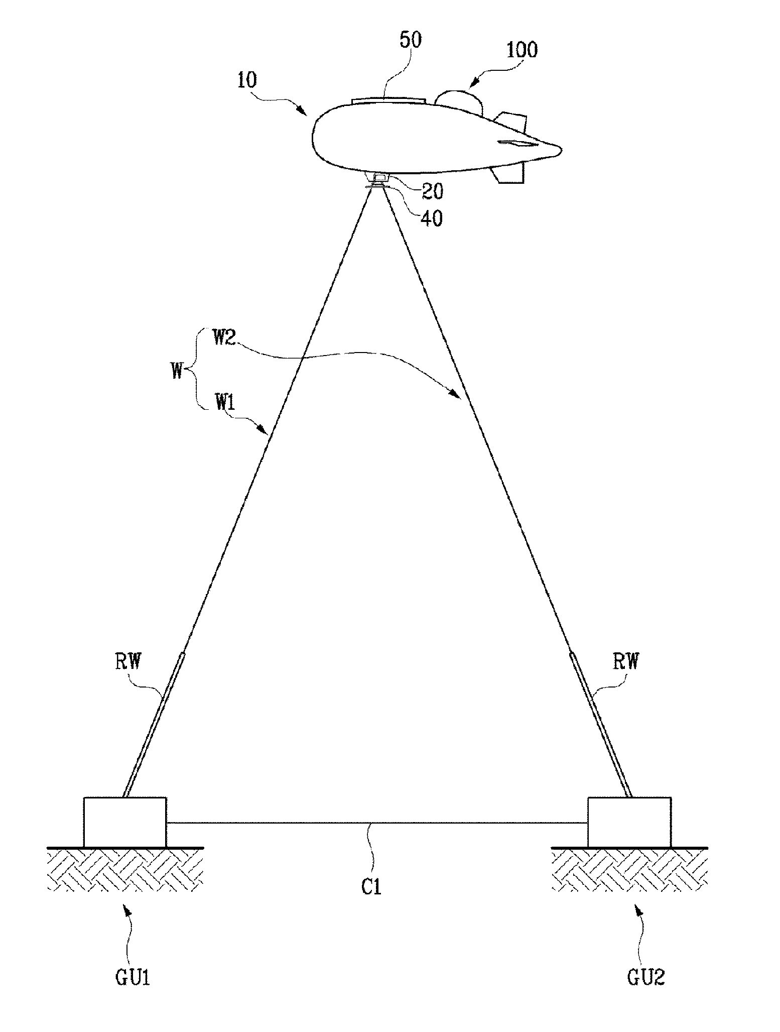
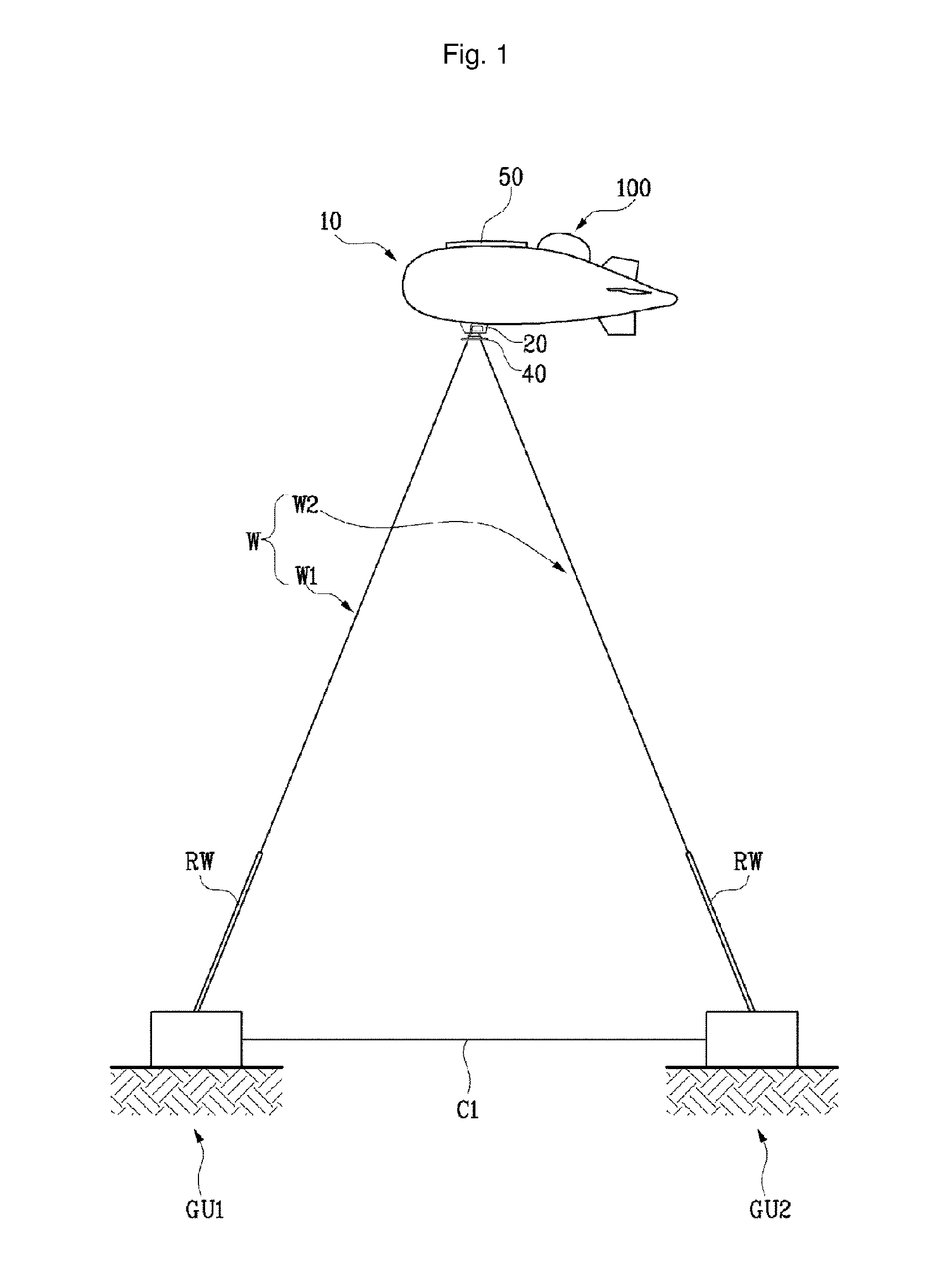
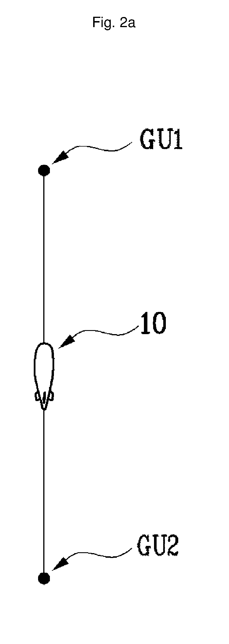
[0089]FIG. 1 is a schematic view illustrating a configuration of a flying object operating system according to an exemplary embodiment of the present invention. FIGS. 2A to 2C are example views illustrating a configuration of a ground unit according to an exemplary embodiment of the present invention. FIG. 4 is a view illustrating a configuration wherein the angle of a buoyancy-generation unit is changed according to an exemplary embodiment of the present invention.

[0090]To this end, the flying object operating system according to the present invention may include, but is not limited to, a flying object 10; ground units GU1 and GU2, and a wire unit “W”, the configuration of each of which will be described in order.

[0091]First, the flying object 10 is provided so as to carry out various missions while staying ...


PUM


Abstract

The present invention relates to a system for operating a flying object that is flown from the ground. The flying object operation system includes a flying object that is filled with a gas therein to stay in the sky, a ground unit installed on the ground, a wire unit connecting the flying object to the ground unit, and a buoyancy-generation unit disposed on a side of the flying object to obtain buoyancy through friction with air, thereby transferring the obtained buoyancy to the flying object. In the present invention, since additional wind-derived buoyancy obtained by the buoyancy-generation unit connected to the flying object is further generated, sufficient buoyancy may be supplied to the flying object in a high-altitude environment to stably operate the flying object. Also, since power generated by using the wind power generation unit is transmitted to the ground through the wire unit, the flying object operation system may be utilized as wind power generation equipment.

Description

TECHNICAL FIELD[0001]The present invention relates to a flying object, and in particular to a flying object operating system which is connected to the ground and is able to receive electric power from the ground and to stay flying at a predetermined position from the ground.BACKGROUND ART[0002]In general, a flying object represents an object which is able to fly in the air and may be categorized into an airship which uses a self-generated power like an airplane and a non-power flying object like a glider.[0003]A towing airship which is a representative of such a non-power flying object is a kind of a flying object which is configured to generate lift from gas in such a way to inject gas lighter than the air into an air sac.[0004]In recent years, a new flying object is being widely used. As an example, the non-power flying object equips with an assistant power device, for example, an engine, etc. so as to generate a propelling force.[0005]The above airship is able to maintain a paral...

Claims


Application Information

Patent Timeline
Patent Type & Authority Applications(United States)
IPC IPC(8): B64C39/02G01C21/00B64F3/02B64B1/12B64D39/00
CPCB64C39/022B64B1/12G01C21/005B64F3/02B64D39/00B64B1/52B64F1/14F03D5/00F05B2240/922Y02E10/70Y02T50/80B64B1/44
Inventor JANG, SOO-YOUNG
Owner JANG SOO YOUNG
Why Eureka
Try Eureka