
Surface mount device type laser module

Inactive Publication Date: 2016-05-05
EVERREADY PRECISION IND
View PDF4 Cites 3 Cited by
  • Summary
  • Abstract
  • Description
  • Claims
  • Application Information

AI Technical Summary

Benefits of technology

The present invention provides a surface mount device type laser module which reduces the overall volume of electronic devices with the laser module and achieves laser diffraction projection efficacy. The laser module can comply with the requirements of plural light sources or plural wavelengths of the modern electronic device. This accelerates the development of handheld devices, wearable devices, and similar electronic devices.

Problems solved by technology

Consequently, the structure of the optical element is also detrimental to miniaturization of the conventional laser module 1.
Consequently, the conventional laser module 1 cannot comply with the requirements of plural light sources or plural wavelengths of the modern electronic device.
Under this circumstance, the development of the handheld device, the wearable device or the comparable electronic device is restricted.

Method used


Image

  • Surface mount device type laser module
  • Surface mount device type laser module
  • Surface mount device type laser module

Examples


Embodiment Construction

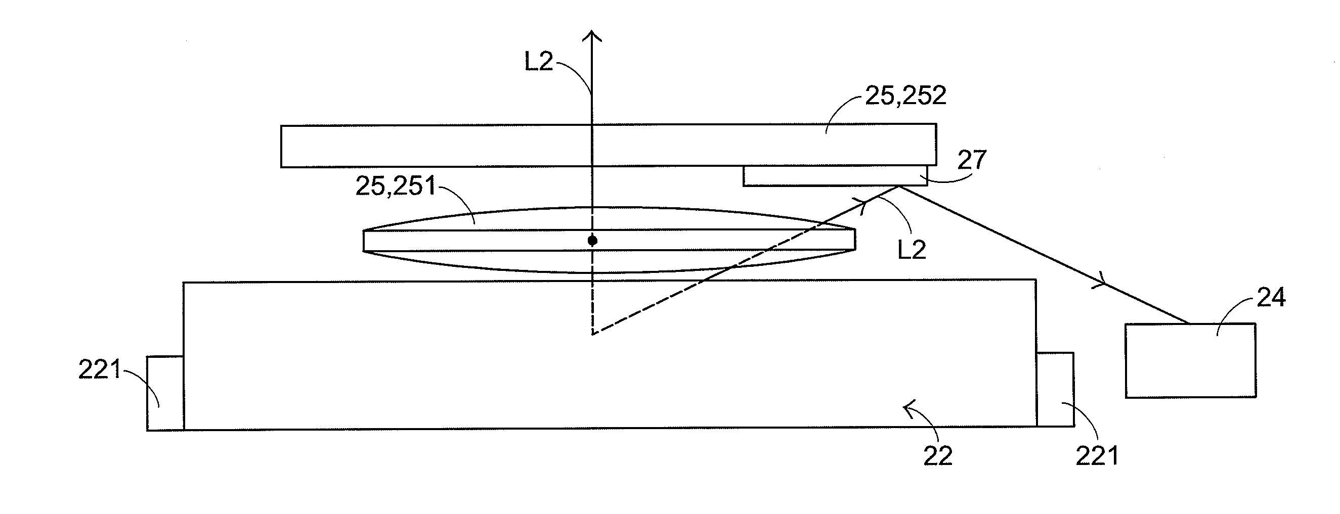
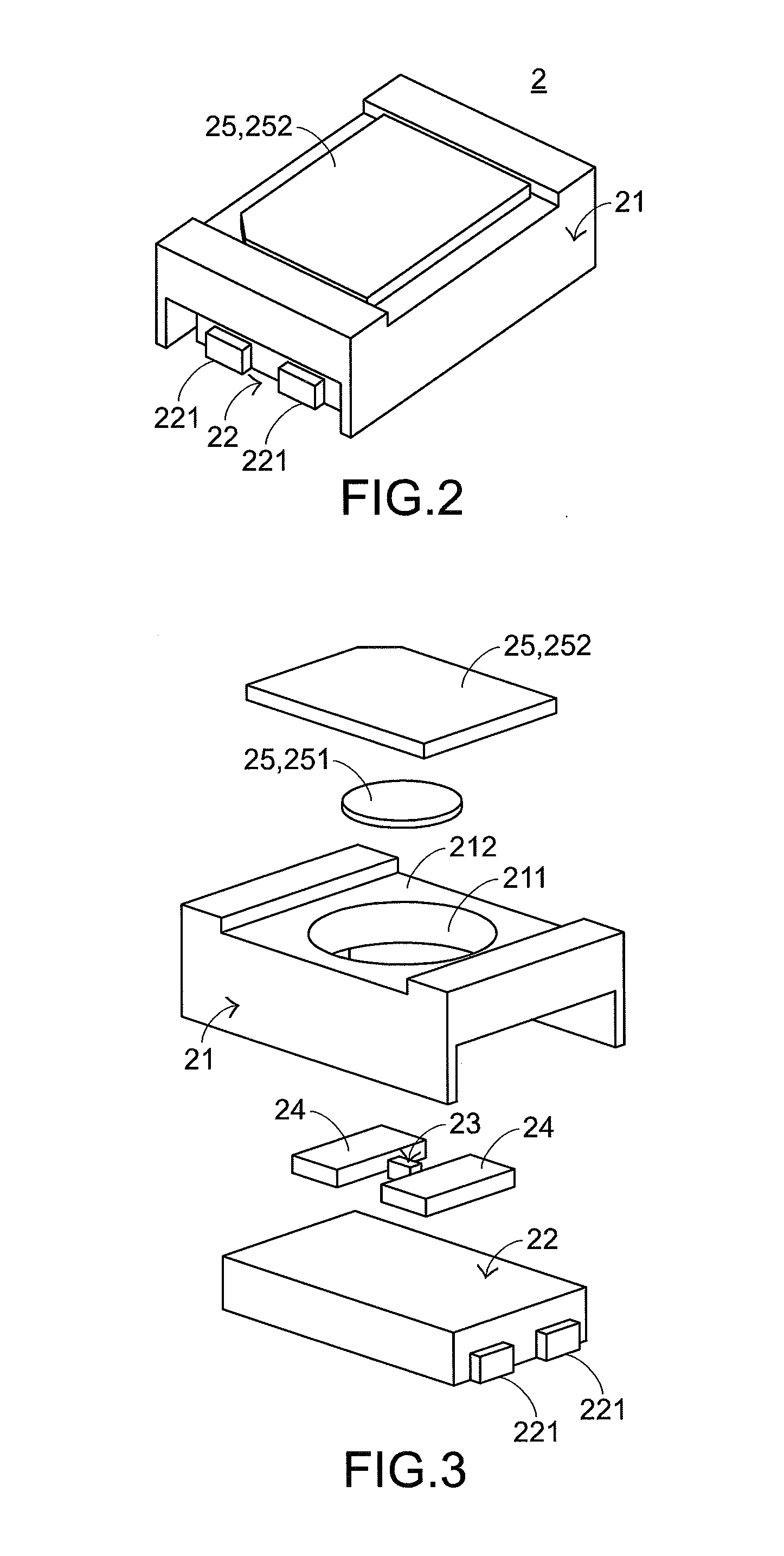
[0030]Please refer to FIGS. 2-4. FIG. 2 is a schematic perspective view illustrating the outer appearance of a surface mount device type laser module according to an embodiment of the present invention. FIG. 3 is a schematic exploded view illustrating the surface mount device type laser module of FIG. 2. FIG. 4 is a schematic front view illustrating a portion of the surface mount device type laser module of FIG. 2. The surface mount device type laser module 2 comprises a housing 21, a base 22, a vertical-cavity surface-emitting laser diode unit (VCSEL) 23, two photodiode units (PD) 24 and plural optical elements 25. The base 22 is accommodated within the housing 21. The base 22 may support one or more vertical-cavity surface-emitting laser diode units 23 and the photodiode units 24. Moreover, the base 22 may provide a flat surface or a recess with a bottom surface in order to fix the one or more vertical-cavity surface-emitting laser diode units 23 and the photodiode units 24. The b...


PUM

PropertyMeasurementUnit
Angleaaaaaaaaaa
Distanceaaaaaaaaaa
Lengthaaaaaaaaaa

Abstract

A surface mount device type laser module includes a housing, a vertical-cavity surface-emitting laser diode, a diffractive optical element and a base. The base is accommodated within the housing, and the vertical-cavity surface-emitting laser diode is integrated into the base. The base includes at least one surface transmission structure. The at least one surface transmission structure is exposed outside the base and the housing. An electronic signal is transmitted through the at least one surface transmission structure. Since the laser module is equipped with the diffractive optical element, the laser diffraction projection efficacy is achieved.

Description

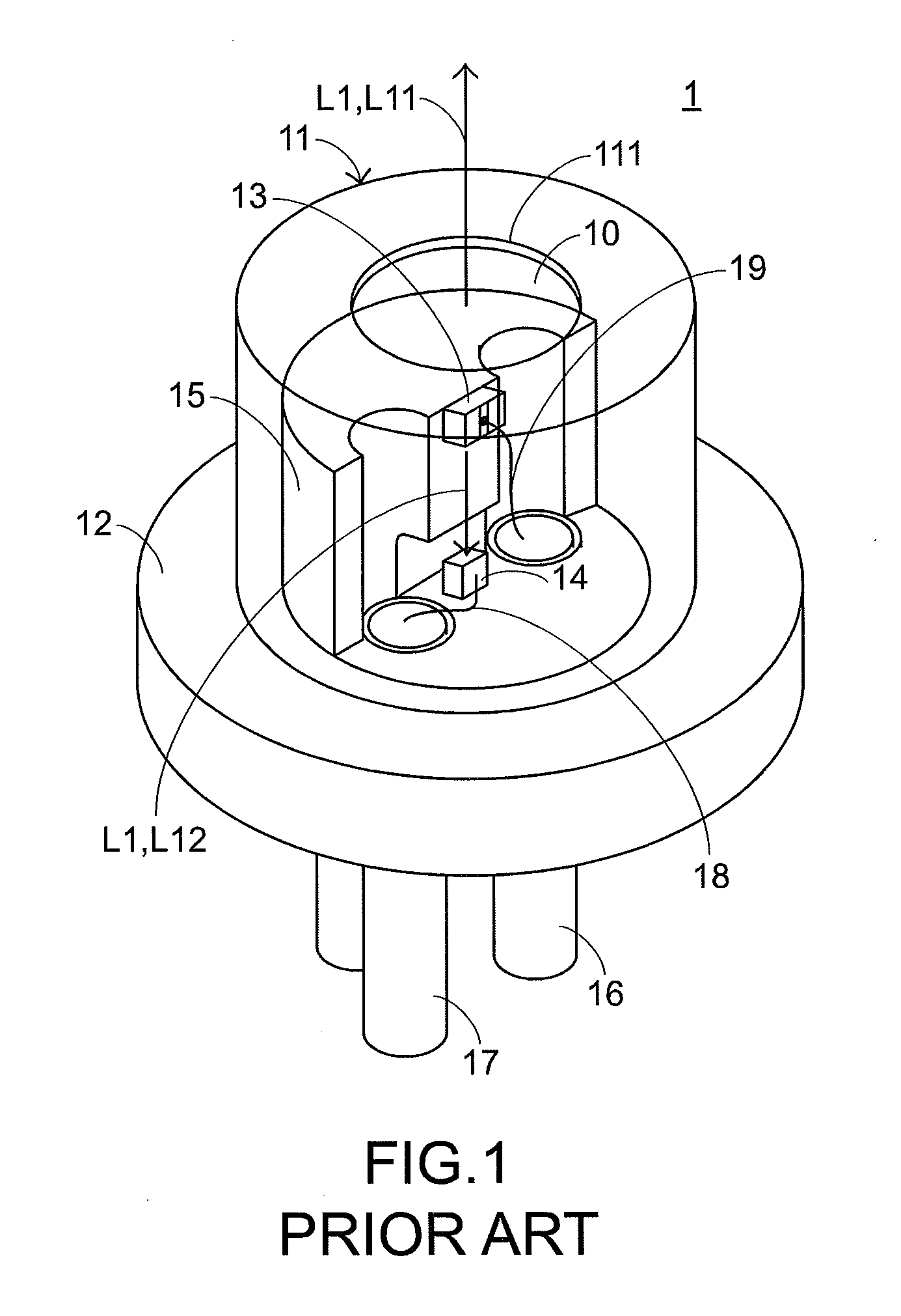
FIELD OF THE INVENTION[0001]The present invention relates to a laser module, and more particularly to a surface mount device type laser module.BACKGROUND OF THE INVENTION[0002]FIG. 1 is a schematic perspective view illustrating a portion of the structure of a conventional laser module. The conventional laser module 1 has a TO-CAN package structure. Moreover, the conventional laser module 1 comprises a casing 11, a base 12, a laser diode 13, a photodiode 14, a heat sink 15, a first pin 16 and a second pin 17. The heat sink 15 and the photodiode 14 are fixed on the base 12. The laser diode 13 is disposed on the heat sink 15. The laser diode 13 and the photodiode 14 are connected with the first pin 16 and the second pin 17 through wires 18 and 19, respectively. The first pin 16 and the second pin 17 are penetrated downwardly through the base 12 and protruded outside. After the first pin 16 and the second pin 17 are penetrated through perforations of an external circuit board (not shown...

Claims


Application Information

Patent Timeline
IPC IPC(8): G02B27/42G02B27/30G02B1/11H01S5/42
CPCG02B27/4233G02B1/11G02B27/30H01S5/423H01S5/02216H01S5/0683H01S5/183H01S5/02253H01S5/02325
Inventor CHERN, JYH-LONGYEN, CHIH-MING
Owner EVERREADY PRECISION IND
Learn More