
Partial Time Active Clamp Flyback

a clamp and active technology, applied in the field of partial time active clamp flyback, can solve the problems of increasing the efficiency of the adapter, the inability of the flyback to reduce standby power, and the loss of more losses than the inefficiency of the unit, so as to achieve the effect of improving efficiency

Inactive Publication Date: 2016-05-05
ROMPOWER TECH HLDG LLC
View PDF4 Cites 6 Cited by
  • Summary
  • Abstract
  • Description
  • Claims
  • Application Information

AI Technical Summary

Benefits of technology

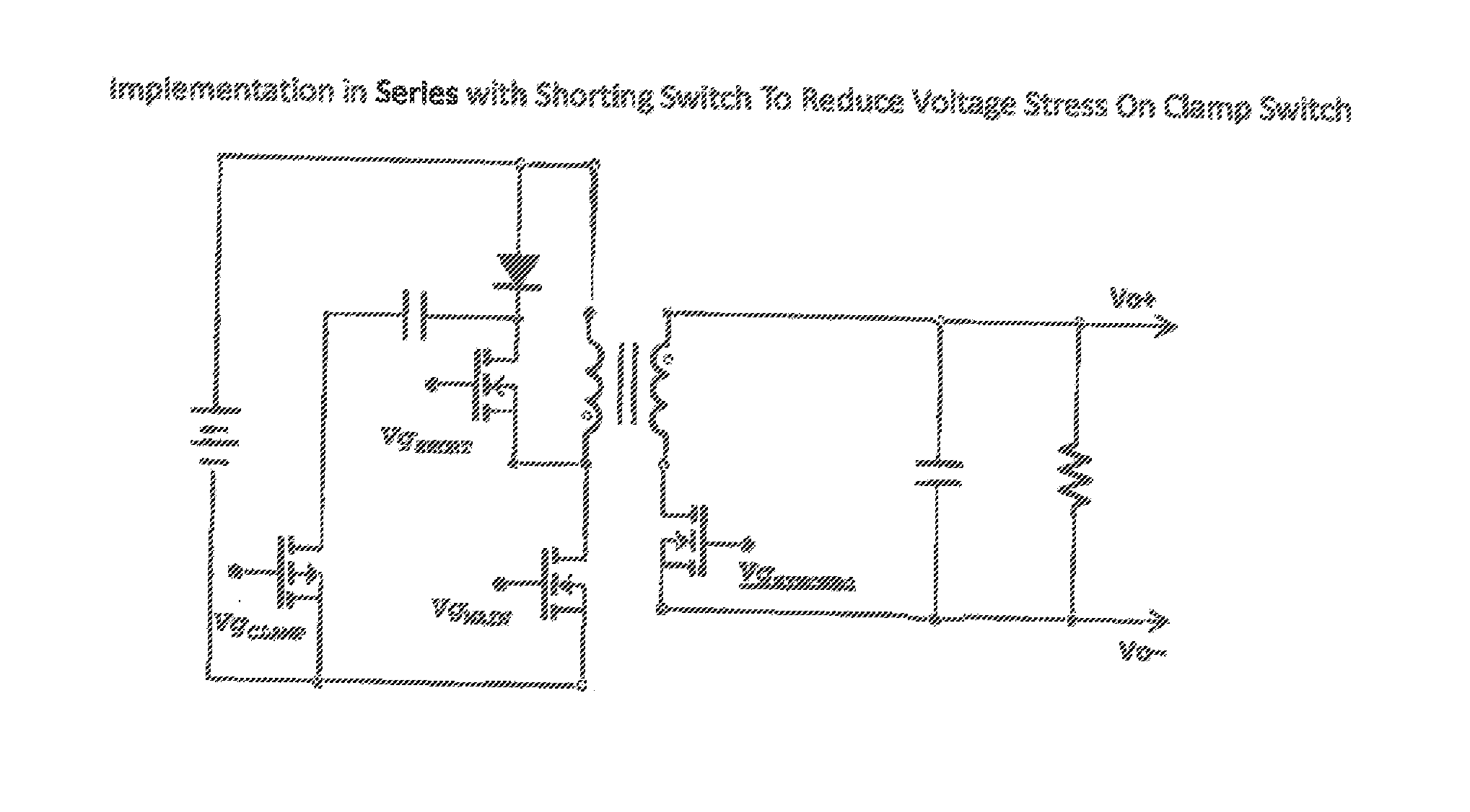
This patent describes a method to improve the efficiency of an inductive power supply circuit by recycling leakage energy and steering current to the secondary. This method involves using an active clamp circuit to store and transfer leakage energy to the secondary during the reset period of the transformer, reducing voltage across the primary switch and minimizing stress on the main switch. Additionally, this method can be combined with another invention to further improve efficiency. Overall, this patent presents a means to enhance the efficiency of inductive power supply circuits.

Problems solved by technology

It has been statically proven that the standby power called vampire power causes more losses than the inefficiency of the unit while charging the mobile device.
In today's modern world of green efficiency and ever reduction in size of mobile devices the Flyback's ability to reduce standby power is not enough.
Not increasing the adapter's efficiency would lead to uncomfortable even dangerous operating temperatures.
The resonant ZVS decreases the power needed to switch the MOSFETS at the cost of increased complexity of finding the valley point in the resonant waveform.

Method used


Image

  • Partial Time Active Clamp Flyback
  • Partial Time Active Clamp Flyback
  • Partial Time Active Clamp Flyback

Examples


Embodiment Construction

2. Active Clamp to Recycle Leakage Energy

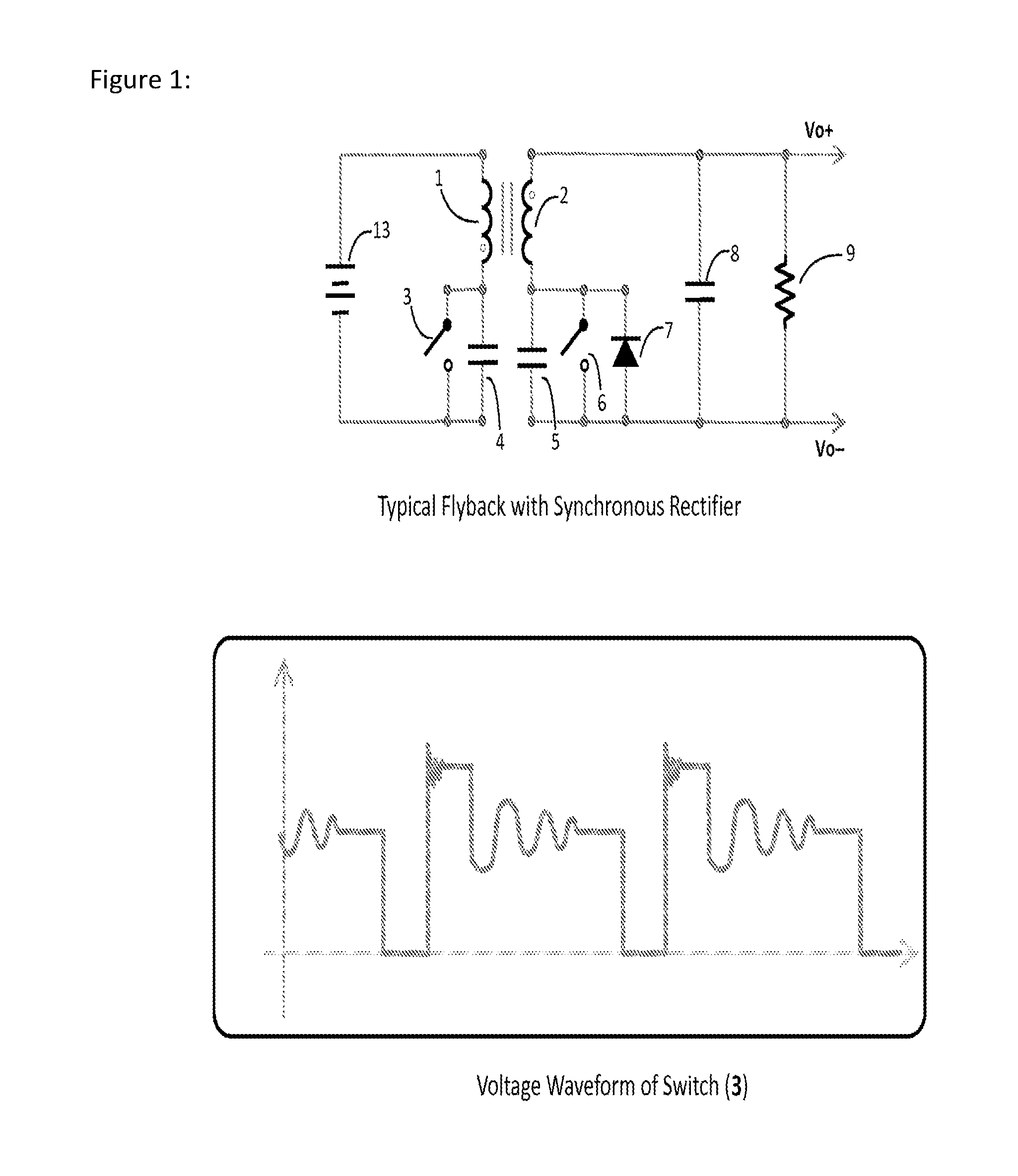
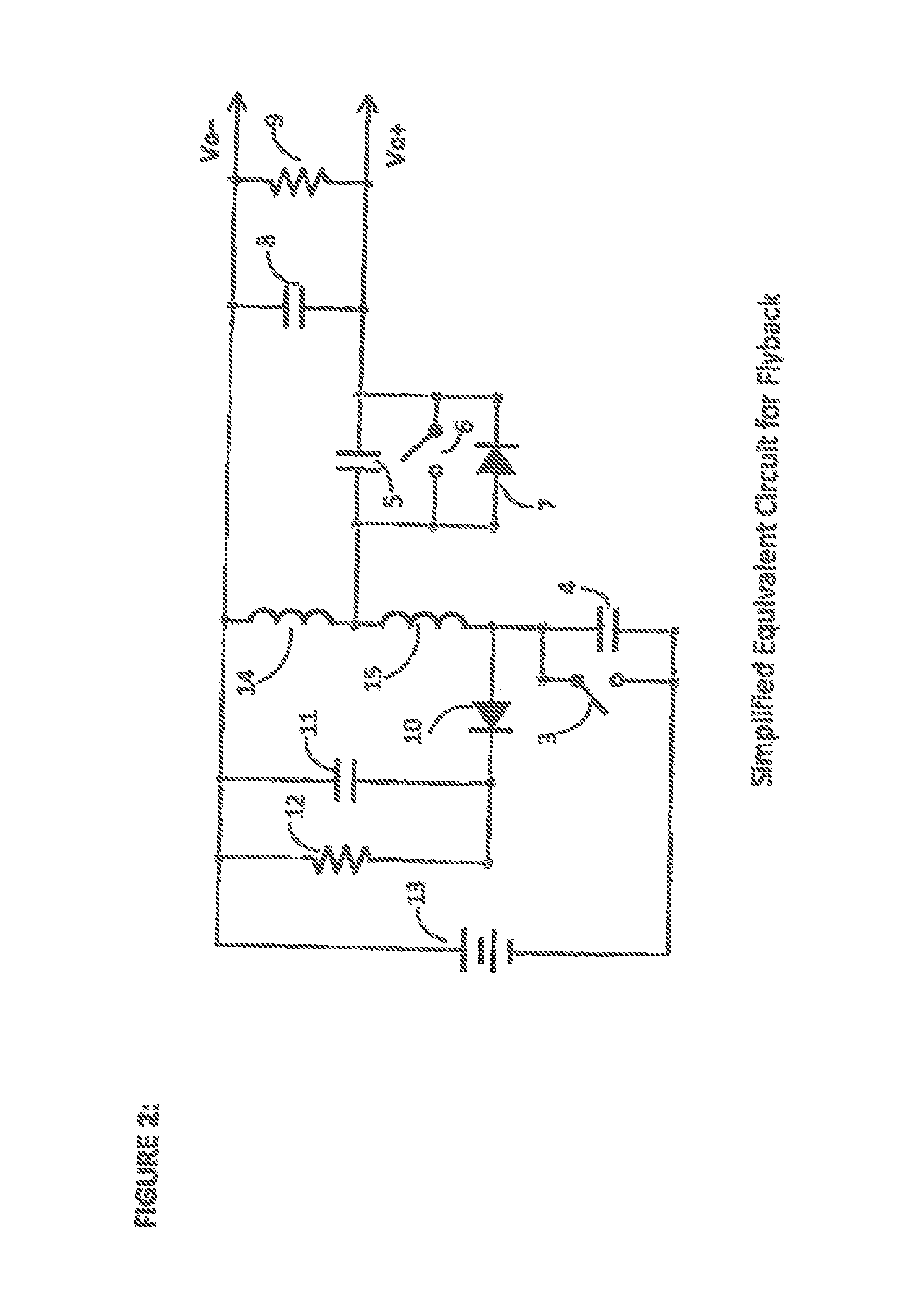
[0024]Presented in FIG. 1 shows a simplified Flyback circuit and its associated voltage waveform of the drain voltage of main primary switch (3). The voltage stress when the switch turns off is the sum of the input voltage, the reflected output voltage, and a leakage inductance spike. The reason there is a spike is that it takes extra voltage to transfer the current flowing in the primary to the secondary. This is caused by the leakage inductance of the transformer. It is part of the inductance of the transformer that is not coupled to the secondary. All transformers consist of two basic modeled components. One is the leakage inductance (15) the other is the mutual inductance (14). The mutual inductance is the component that allows current to move between primary and secondary while the leakage inductance resists the movement. The equivalent circuit is shown in FIG. 2 with a typical clamp circuit.

[0025]To deal with the voltage spike a clamp c...


PUM


Abstract

A method is shown to improve the resonant transition controlled flyback converter presented in Ser. No. 14 / 274,598 (Exhibit A) by adding a clamp circuit that recycles the leakage energy. By utilizing the particular advantages of the resonant transition controlled flyback converter an optimized clamp capacitor can be used to increase the efficiency of the converter further.

Description

RELATED APPLICATION / CLAIM OF PRIORITY[0001]This application is related to and claims priority from U.S. provisional application Ser. No. 62 / 075,518, filed Nov. 5, 2014, and which provisional application is incorporated by reference herein.INTRODUCTION AND SUMMARY OF THE PRESENT INVENTION[0002]The Flyback converter is the most popular converter for off line applications. Applications include AC to DC adapters for laptops, tablets, cellular phones, and many other portable devices. Key to the Flyback topology's popularity is a simple design offering a wide operating range compared to other topologies. Also, in discontinuous mode the Flyback converter has discrete energy packets leading to higher efficiency at low output power. High efficiency at low output power is vitally important because the adapter is used for charging mobile devices and the majority of the users will leave an adapter plugged in requiring the adapter to be in standby or low power output mode. It has been statically...

Claims


Application Information

Patent Timeline
Patent Type & Authority Applications(United States)
IPC IPC(8): H02M3/335
CPCH02M3/33592H02M3/33569Y02B70/10
Inventor DAVILA, MARCO ANTONIO
Owner ROMPOWER TECH HLDG LLC
Learn More