Powder dispenser for making a component by additive manufacturing

a technology of additive manufacturing and dispensers, applied in the field of additive manufacturing, can solve the problems of insufficient satisfaction, relative great amount of time, and scarcely satisfactory known solutions of the type described above, and achieve the effect of simple and cost-effectiv

Active Publication Date: 2016-05-12
SBC KNOWLEDGE VENTURES LP +1
View PDF11 Cites 66 Cited by
  • Summary
  • Abstract
  • Description
  • Claims
  • Application Information

AI Technical Summary

Benefits of technology

[0011]The object of the present invention is to provide a powder dispenser for making a component by add

Problems solved by technology

However, the final component obtained by this process occupies a very small part of said volume, for example 10%; therefore, a large quantity of powder is necessary for each component to be made.
Even though the residual powder is recovered, known solutions of the type described above are scarcely satisfactory, since the large quantity of powder needed leads to the use large containers for the storage t

Method used


Image

  • Powder dispenser for making a component by additive manufacturing
  • Powder dispenser for making a component by additive manufacturing
  • Powder dispenser for making a component by additive manufacturing

Examples


Embodiment Construction

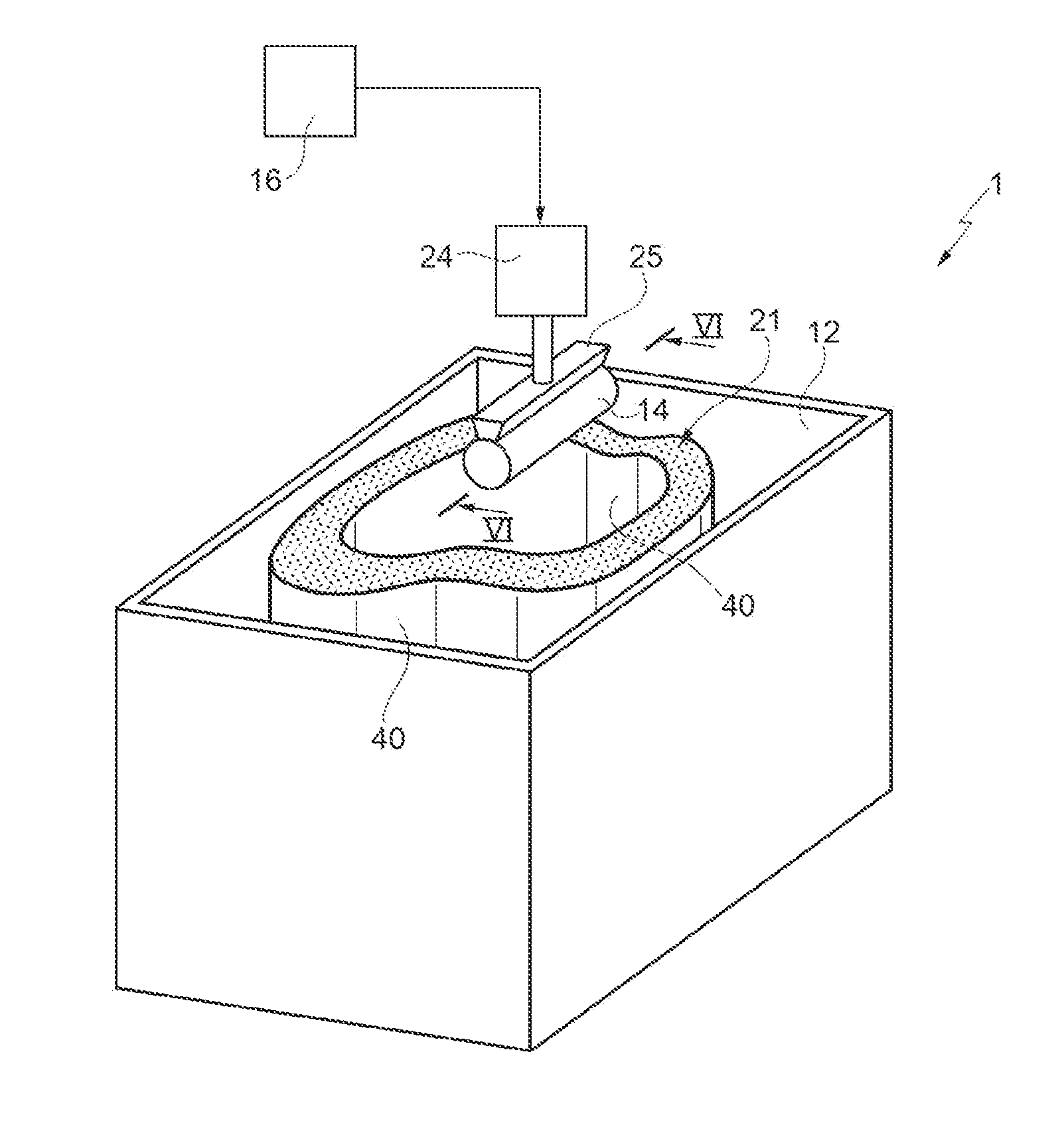
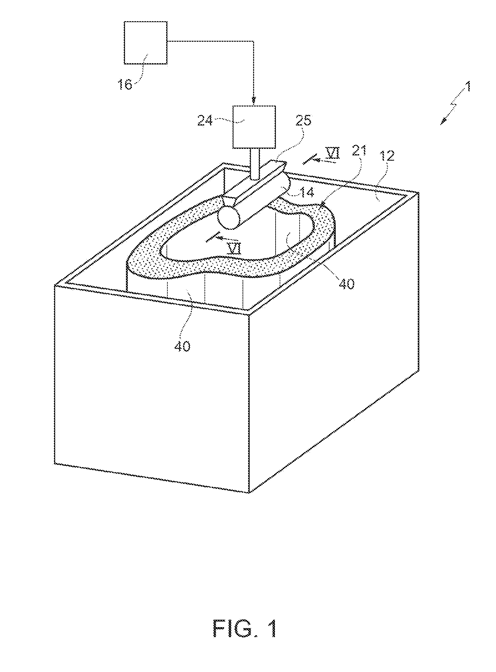
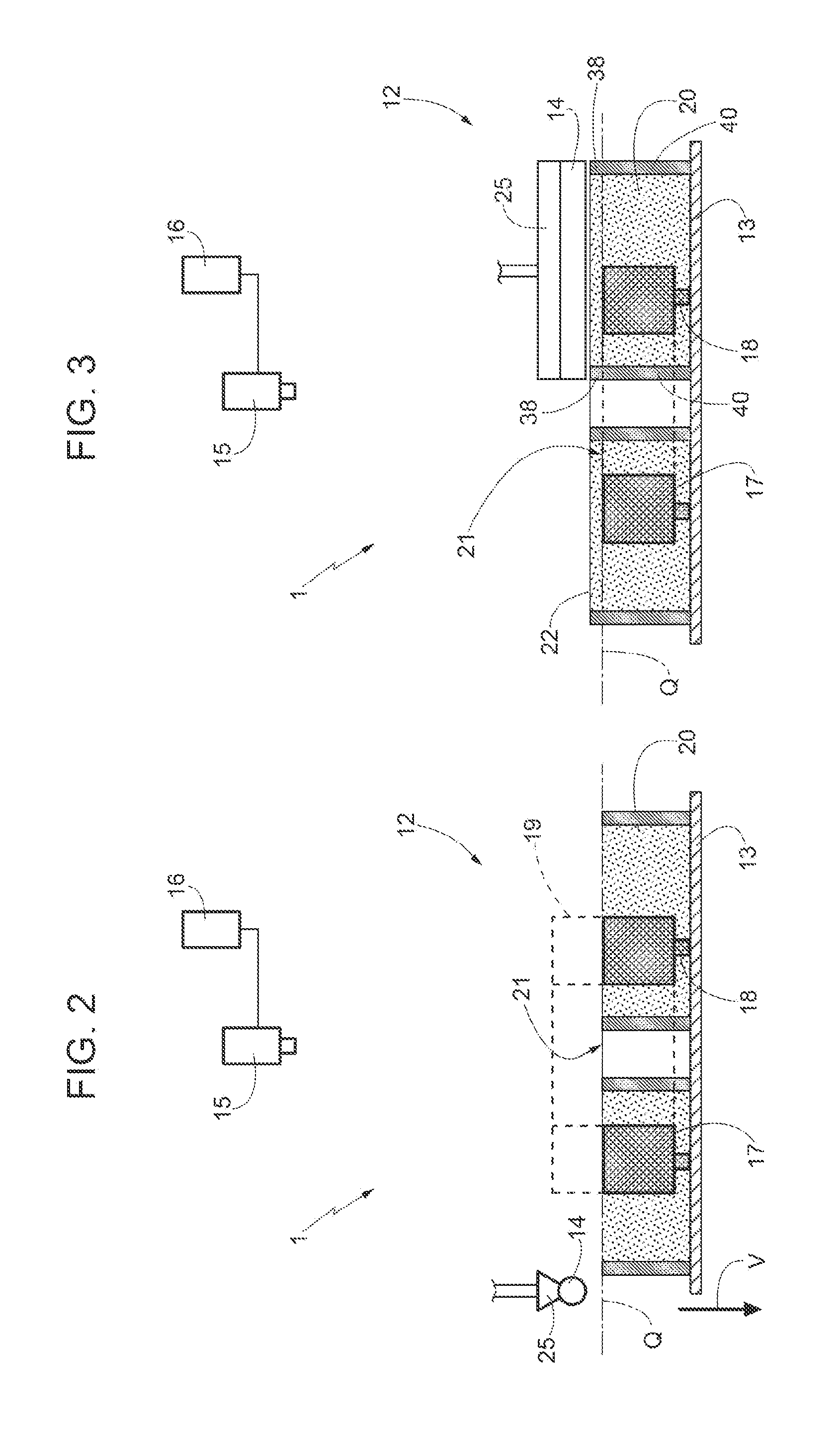
[0018]In FIGS. 1 to 5, reference number 1 indicates, as a whole, a (partially and schematically shown) machine for making a component starting from powder, in particular metal powders, by an additive manufacturing technique, namely a manufacturing technique of the type “layer by layer”. These layer-by-layer manufacturing techniques are known and are mentioned in printed materials with different acronyms, for example acronyms such as “Direct Laser Forming” (DLF), “Direct Metal Laser Sintering” (DMLS), “Selective Laser Melting” (SLM), ∘“Electron Beam Melting” (EBM).

[0019]The composition of the powder is the same as that of the component to be formed. In particular, in the aeronautical field, people commonly use titanium alloys or titanium-aluminium alloys, for example an alloy known with the abbreviation Ti6-4 or Ti-6Al-4V (having 6% of aluminium and 4% of vanadium). As far as titanium alloys are concerned, the temperatures needed to obtain the melting of the powder can reach up to 18...


PUM

PropertyMeasurementUnit
Lengthaaaaaaaaaa

Abstract

A powder dispenser (14) has a vertical channel (55), which, at the top, is adapted to communicate with a tank for receiving the powder and inferiorly ends at an opening (26), which is elongated along a horizontal direction and comprises an outlet portion (51) for letting the powder fall; the dispenser further has a shutter device (50) for varying the length of the outlet portion (51) with respect to the total length of the opening (26) along its horizontal axis (36).

Description

[0001]The present invention relates to a powder dispenser for making a component by additive manufacturing.BACKGROUND OF THE INVENTION[0002]As it is known, additive manufacturing techniques involve the repetition of cycles, during which successive horizontal sections of the component to be made are formed. In particular, at the beginning of each cycle, a layer of powder is deposited by means of a dispenser, which is able to translate horizontally. This layer of powder has a substantially constant thickness and the powder has the same composition as the component to be made. After the layer of powder has been deposited, specific area thereof are melted through the scanning of a focused energy beam, typically a laser beam or an electron beam. In those areas where the powder is melted, a continuous, solid structure is formed, which defines a corresponding horizontal section of the component. These areas are selected by a control unit according to a mathematical model, which represents ...

Claims


Application Information

Patent Timeline
IPC IPC(8): B22F3/105
CPCB22F3/1055B33Y30/00B22F2003/1056B22F10/00B22F12/222B22F12/67B22F12/63B22F10/28B22F12/226B29C31/02B29C31/044B29C64/153B29C64/214B29C64/255B29C64/268B29C64/321Y02P10/25
Inventor VARETTI, MAURO
Owner SBC KNOWLEDGE VENTURES LP
Why Eureka
Try Eureka