Washing machine driving device, washing machine having same, and control method therefor

Active Publication Date: 2016-05-12
AMOTECH
View PDF0 Cites 30 Cited by
  • Summary
  • Abstract
  • Description
  • Claims
  • Application Information

AI Technical Summary

Benefits of technology

[0052]The present invention is configured to independently control directions of rotation and rotational speeds of a pulsator and a washing tub, respectively, to thus form a variety of water flow patterns, improve a cleaning capability, improve fabric loose performance, prevent fabric tangling, enable rhythm washability, and control the water flow intensity.
[0053]The present invention is configured to start one having a larger starting torque of a pulsator and a washing tub earlier than the other thereof to then be rotatabl

Problems solved by technology

For this reason, the conventional combination dehydration full-automatic washing machine has quite a complex configuration to thus cause poor manufacturability and assembly performance and to resultantly increase manufacturing cost.
In addition, a control circuit transmission path switching operation does not work in progress due to the poor manufacturing accuracy and deterioration over time of the clutch mechanism to thereby cause unstable switching reliability in some cases.
Moreover, during performing a switching operation from a washing operation to a dehydration operation, there is a noise problem caused by a switching operation sound of the clutch mechanism or an operation sound generated from the reduction mechanism.
In addition, there is a problem that a long laundry time is taken due to a prolonged switching operation of the clutch mechanism.
The above-described conventional full-automatic washing machine is provided with a clutch motor to ensure that power is selectively transmitted to the washing shaft and the dehydration shaft, to accordingly cause a problem that the dehydration tub and pulsator cannot be driven independently and thus a variety of water flows cannot be formed.
In addition, in Patent Document 1, since the washing stroke of low-speed and high-torque characteristics and the dehydration stroke of high-speed and low-torque characteristics should be performed by using a single d

Method used


Image

  • Washing machine driving device, washing machine having same, and control method therefor
  • Washing machine driving device, washing machine having same, and control method therefor
  • Washing machine driving device, washing machine having same, and control method therefor

Examples


first embodiment

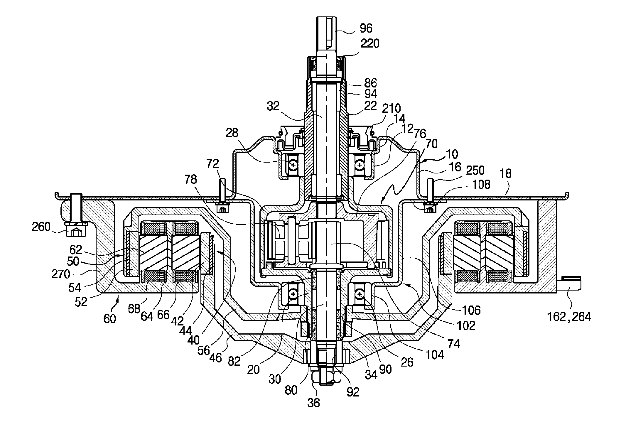
[0076]In the first embodiment, a planetary gear set 70 is mounted on the inner shafts 30 and 32 and increases the torque by accelerating the rotational speed of the inner shafts 30 and 32, to then transfer the increased torque 130 to the pulsator 130.

[0077]The outer shafts 20 and 22 are formed in a cylindrical shape so that the inner shafts 30 and 32 pass through the outer shafts 20 and 22, respectively, and include a first outer shaft 20 coupled to the outer rotor 50, and a second outer shaft 22 coupled to the washing tub 120.

[0078]Then, the inner shafts 30 and 32 include a first inner shaft 30 coupled to the inner rotor 40 and a second inner shaft 32 coupled to the pulsator 130.

[0079]As shown in FIGS. 3 and 4, the planetary gear set 70 includes: a ring gear 72 connecting between the first outer shaft 20 and the second outer shaft 22; a sun gear 74 integrally coupled to the first inner shaft 30; a plurality of planetary gears 78 engaged with an outer surface of the sun gear 74 and ...

second embodiment

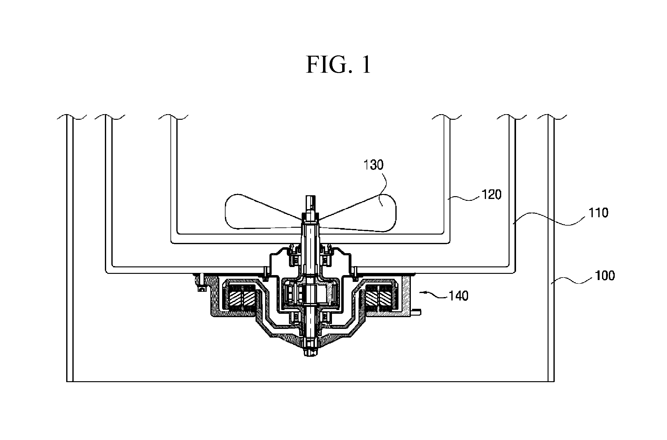
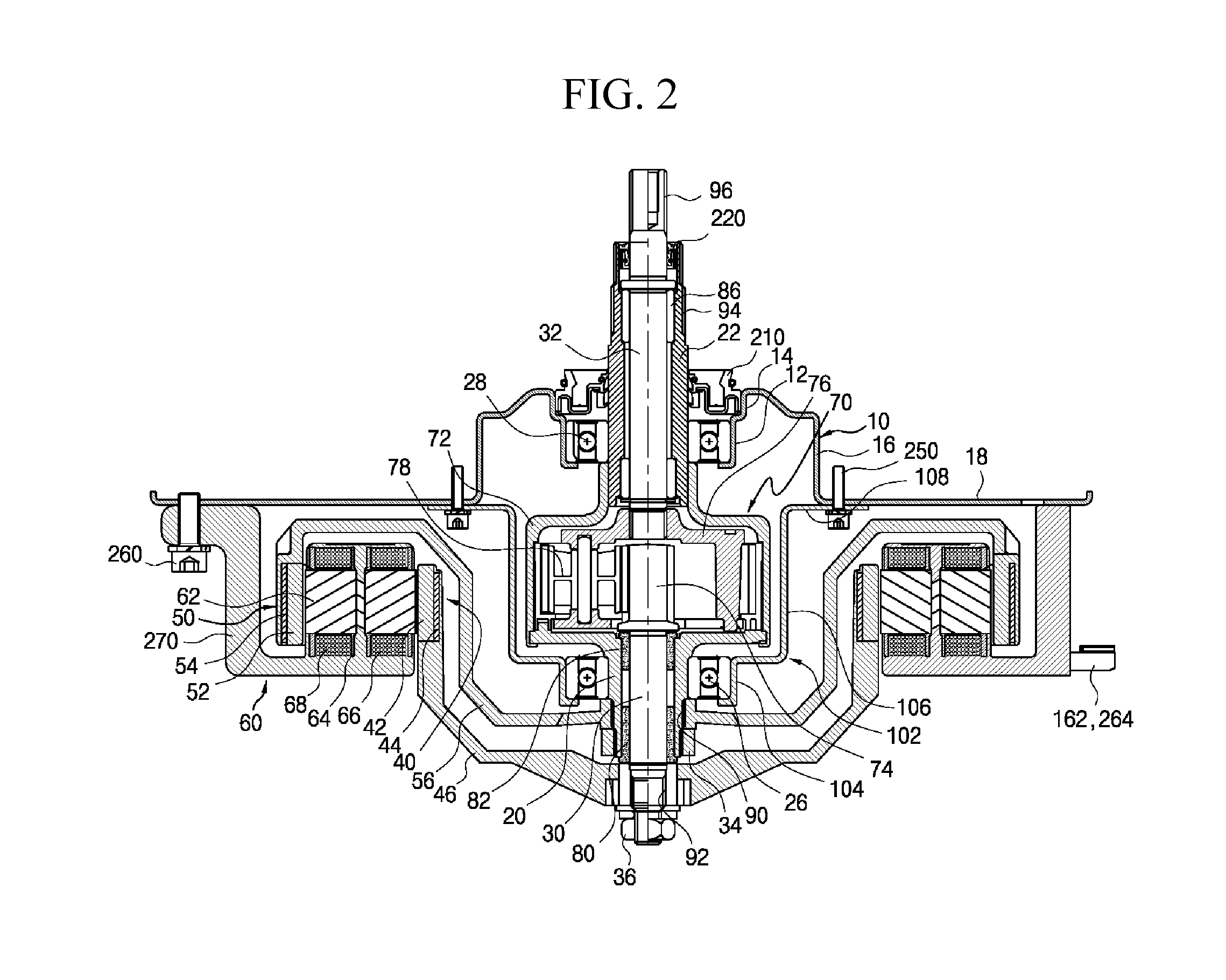
[0131]FIG. 10 is a sectional view of a washing machine motor according to the present invention.

[0132]The washing machine motor 140 according to the second embodiment includes: outer shafts 20 and 22 which are connected with a washing tub 120; inner shafts 30 and 32 which are rotatably arranged inside the outer shafts 20 and 22 and connected with a pulsator 130; an inner rotor 40 which is connected with the outer shafts 20 and 22; an outer rotor 50 which is connected to the inner shafts 30 and 32; a stator 60 which is disposed with an air gap between the inner rotor 40 and the outer rotor 50, to thus independently rotatably drive the inner rotor 40 and the outer rotor 50; and a planetary gear set 70 that is mounted the inner shafts 30 and 32 to thus slow down the rotational speed of the inner shafts 30 and 32 and increase the torque.

[0133]When comparing the washing machine motor 140a according to the second embodiment with the washing machine motor 140 according to the first embodim...


PUM


Abstract

An apparatus for driving a washing machine in which a washing tub and a pulsator are driven separately to thereby form a variety of washing water flows includes: an outer shaft whose one end is connected to a washing tub; an inner shaft whose one end is connected to a pulsator; a planetary gear set that decelerates a rotational speed that is transferred via the inner shaft; first and second bearings that rotatably support the planetary gear set in two-way directions; and a washing machine motor for applying a rotational force to each of the outer shaft and the inner shaft. The washing machine motor includes: an outer rotor; an inner rotor; and a double stator that rotatably drives the outer rotor and the inner rotor independently, in which the output of the pulsator is accelerated or decelerated depending on the direction of rotation of the outer rotor.

Description

TECHNICAL FIELD[0001]The present invention relates to an apparatus for driving a washing machine in which a washing tub and a pulsator are driven separately to thereby form a variety of laundry and washing water flows, a washing machine using the same, and a controlling method thereof.BACKGROUND ART[0002]A conventional combination dehydration full-automatic washing machine is configured to include a rotating tub rotatably installed in an outer tub as a combination dehydration tub and washing tub, and further include a pulsator rotatably mounted on the bottom portion of the rotating tub. Since the pulsator and the rotating tub are rotatably driven by a single drive motor, rotation of the drive motor is transferred to the pulsator in a state where the rotating tub is braked and stopped, to thus make the pulsator driven in forward and reverse rotation modes at a relatively low speed, when running a washing operation. Meanwhile, when running a dehydration operation, braking of the rotat...

Claims


Application Information

Patent Timeline
IPC IPC(8): D06F37/30H02K16/00H02K7/116
CPCD06F37/304H02K16/00H02K7/116H02K16/02D06F37/40D06F17/06D06F37/269Y02B40/00D06F33/36D06F2105/46
Inventor SONG, DUCK HYUN
Owner AMOTECH
Why Eureka
Try Eureka