Optical receptacle

a technology of optical communication and optical fiber, applied in the field of optical transceiver module for optical communication, can solve the problems of many cracks, fiber breaking, and economic production being extremely difficult, and achieve the effects of preventing breaking and cracks, shortening the total length of the optical module, and ensuring the strength of the deformable portion of the optical fiber

Active Publication Date: 2016-05-12
TOTO LTD
View PDF13 Cites 9 Cited by
  • Summary
  • Abstract
  • Description
  • Claims
  • Application Information

AI Technical Summary

Benefits of technology

[0012]To solve the problems recited above, embodiments of the invention are directed to provide an optical receptacle in which, by making the core small at the optical element side end surface of the optical fiber while contributing to shortening the optical module total length, the strength of the deformable portion of the optical fiber can be ensured; the occurrence of breaking and cracks can be prevented; and the decrease of the coupling efficiency can be prevented by suppressing the movement of the optical fiber when using the optical module.

Problems solved by technology

However, as in FIG. 1 or FIG. 2 of Patent Citation 2, normally, although it is necessary to locally add a refractive index control additive to the fiber to convert the core diameter while the outer diameter of the normal fiber remains constant, in this method, there is a problem of economic production being extremely difficult not only because the work method is complex but also because the control items are extremely numerous.
Also, unlike the description recited above, although it is possible to produce economically in the case where the outer diameter of the fiber tip changes and the core diameter of the tip portion changes as in FIG. 3, there is a problem of the fiber breaking and many cracks occurring because the portion that is exposed outside the ferrule has a lower strength due to the smaller outer diameter of the fiber due to the changing core diameter of the fiber end surface.

Method used


Image

  • Optical receptacle
  • Optical receptacle
  • Optical receptacle

Examples


first embodiment

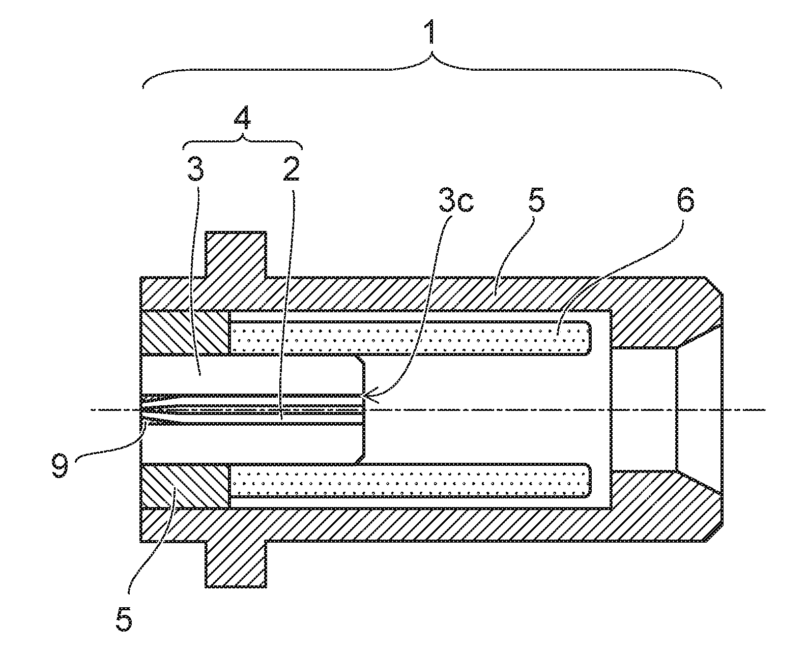
[0037]FIG. 1 is a schematic cross-sectional view of an optical receptacle showing the invention.

[0038]The optical receptacle 1 is made of a fiber stub 4, a holder 5 holding the fiber stub 4, and a sleeve 6, where the fiber stub 4 includes an optical fiber 2, a ferrule 3 having a through-hole 3c holding the optical fiber 2, and an elastic member 9, one end of the sleeve 6 is capable of holding a tip of the fiber stub 4, one other end of the sleeve 6 is capable of holding the plug ferrule inserted into the optical receptacle 1, and the optical fiber 2 is fixedly adhered using the elastic member 9 in the through-hole 3c of the ferrule 3. The plug ferrule that is inserted into the optical receptacle 1 is not shown.

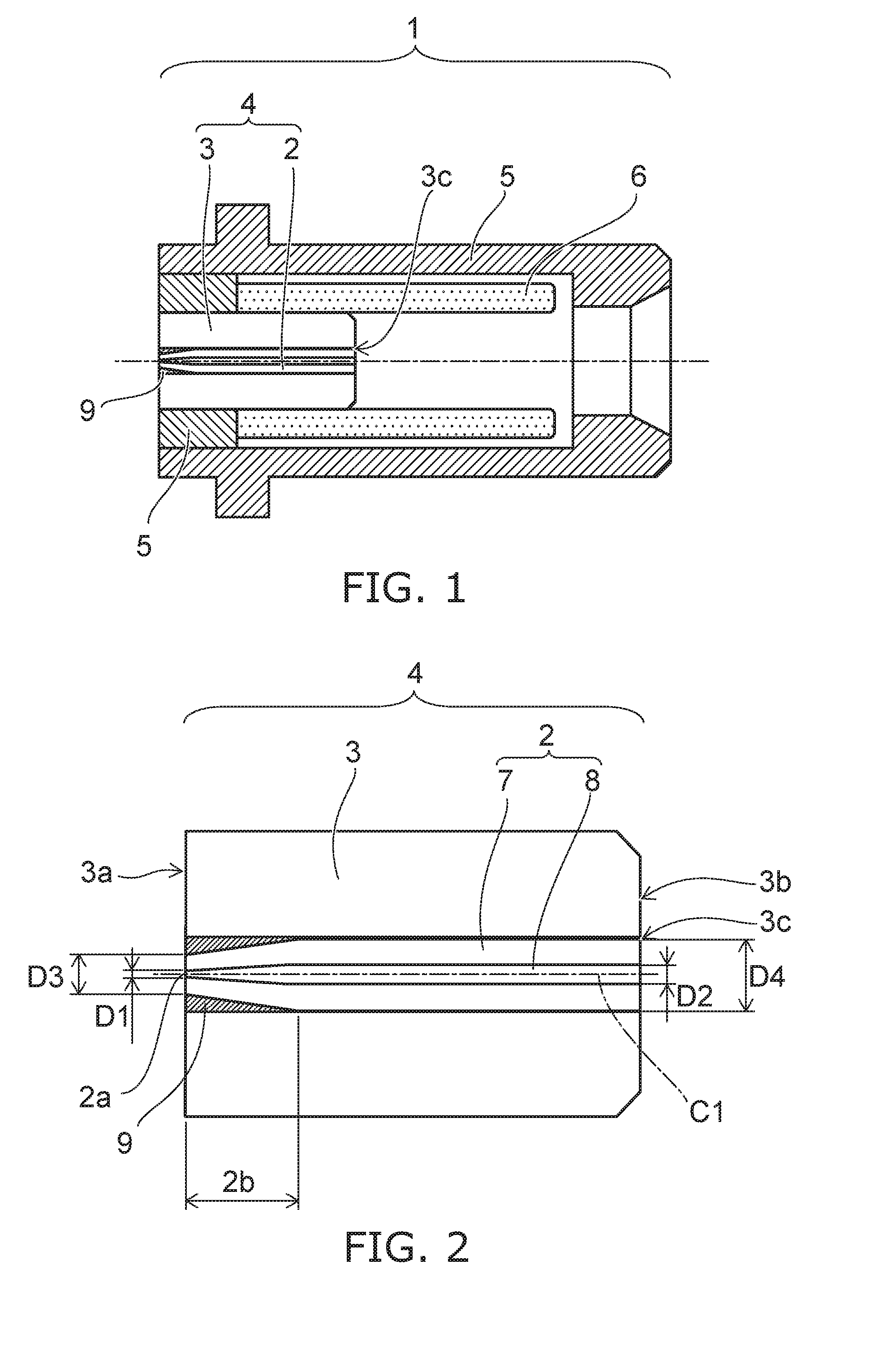
[0039]Although materials suited to the ferrule 3 include a ceramic, glass, etc., a zirconia ceramic is used in the example; the optical fiber 2 is fixedly adhered in the center of the ferrule 3; and one end (an end surface 3b: referring to FIG. 2) to be optically connected to ...

second embodiment

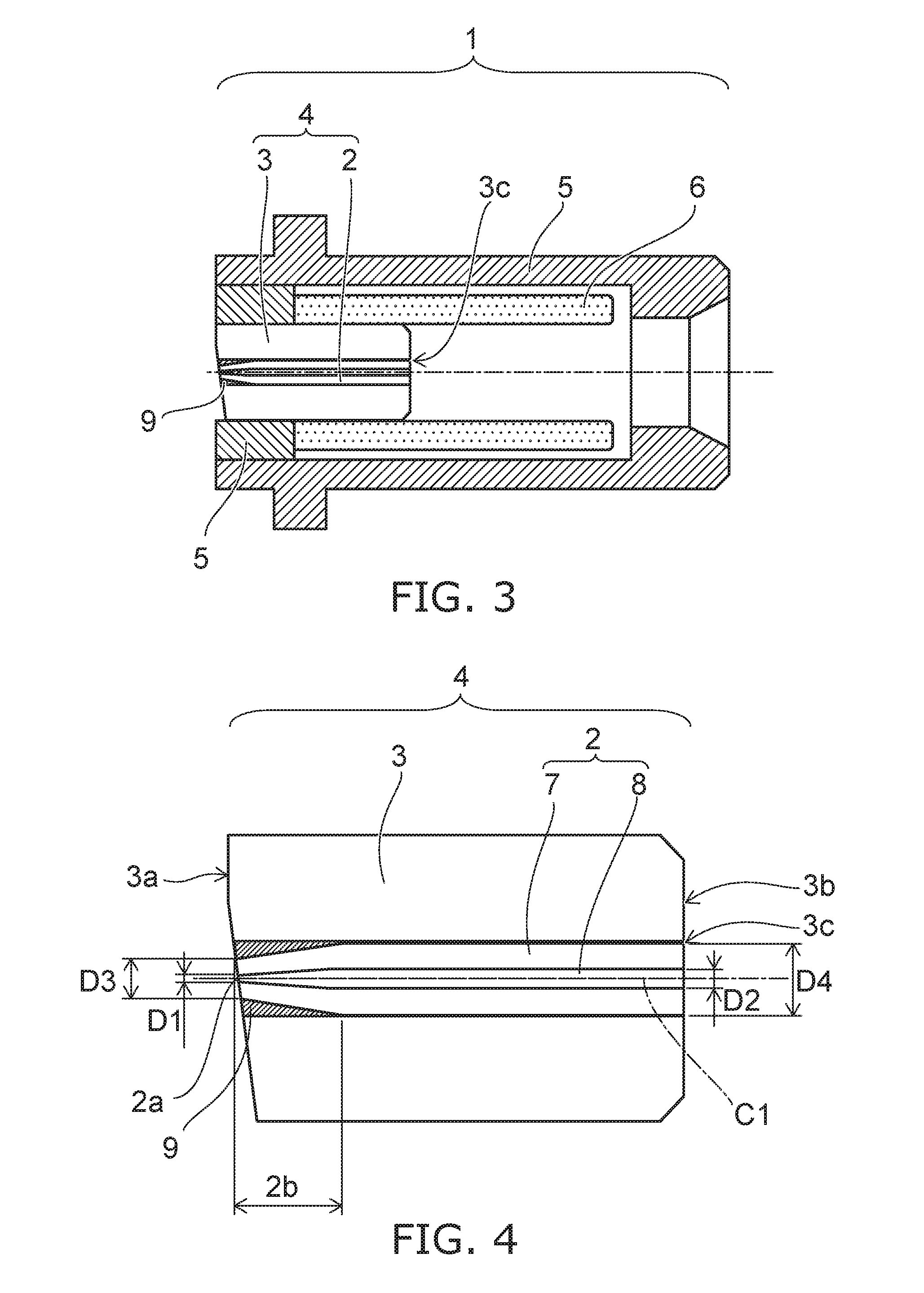
[0052]FIG. 3 is a schematic cross-sectional view of an optical receptacle showing the invention.

[0053]The members included in the optical receptacle 1 are similar to those of the first embodiment; and the end surface 2a of the optical fiber 2 and a portion of the end surface 3b of the ferrule 3 are polished to be flat surfaces having prescribed angles (e.g., 4 degrees to 10 degrees) from a plane perpendicular to the central axis C1 of the ferrule 3 at the end surface 3a (referring to FIG. 4) on the side opposite to the end surface 3b (referring to FIG. 4) polished into the convex spherical surface of the ferrule 3 including the optical fiber 2 and the through-hole 3c holding the optical fiber 2.

[0054]Thereby, similarly to the first embodiment, because the entire portion of the optical fiber 2 where the fiber outer diameter D3 decreases gradually is contained inside the through-hole 3c of the ferrule 3 and the periphery is further covered with the elastic member 9 as the bonding agen...

third embodiment

[0062]FIG. 5 is a schematic cross-sectional view of an optical pigtail module showing the invention.

[0063]As shown in FIG. 5, the configuration of the invention is applicable to an optical pigtail module 10, etc., as well. Thereby, it is possible to set the total length of the optical pigtail module 10 to be short, maintain the strength of the optical fiber 2, and prevent breaking and cracks.

[0064]An investigation relating to the core diameter of the optical fiber implemented by the inventor will now be described with reference to the drawings.

[0065]FIG. 6 is a schematic view showing an example of analysis conditions and analysis results relating to the core diameter.

[0066]FIG. 6A is a schematic cross-sectional view showing the optical fiber used in the investigation. FIG. 6B is a table showing an example of the results of the investigation. FIG. 6C is a graph showing an example of the results of the investigation.

[0067]In the embodiment as described above in reference to FIG. 2 and...


PUM


Abstract

According to an aspect of the invention, an optical receptacle, comprising: a fiber stub including an optical fiber, a ferrule, and an elastic member, the optical fiber including cladding and a core conducting light, the ferrule having a through-hole fixing the optical fiber, the elastic member fixing the optical fiber in the ferrule; and a holder holding the fiber stub, the optical fiber being disposed inside the through-hole over an entire region of the optical fiber, the optical fiber including a portion, a core diameter and a fiber outer diameter in the portion decreasing gradually toward an end surface of the ferrule on a side opposite to a side to be optically connected to a plug ferrule, the elastic member being filled into a space between the optical fiber and an inner wall of the through-hole. By making the core small at the optical element side end surface of the optical fiber while contributing to shortening the optical module total length, the strength of the deformable portion of the optical fiber can be ensured; the occurrence of breaking and cracks can be prevented; and the decrease of the coupling efficiency can be prevented by suppressing the movement of the optical fiber when using the optical module.

Description

TECHNICAL FIELD[0001]Embodiments of the invention relate generally to an optical transceiver module for optical communication and relate particularly to an optical receptacle favorable for a high-speed communication module.BACKGROUND ART[0002]An optical receptacle is used as a component for optically connecting an optical fiber connector to an optical element such as a light receiving element, a light emitting element, etc., in an optical module of an optical communication transceiver (e.g., referring to Patent Citation 1).[0003]In recent years, it is necessary to increase the speed of optical communication transceivers as IP traffic increases. Generally, the configurations of the transceiver and the like that employ the receptacle-type optical module are standardized; and it is necessary to downsize the optical module because the space necessary for the electronic circuit increases as the modulation rate of the optical signal emitted from a semiconductor laser which is one optical ...

Claims


Application Information

Patent Timeline
Patent Type & Authority Applications(United States)
IPC IPC(8): G02B6/38G02B6/42
CPCG02B6/3846G02B6/421G02B6/3822G02B6/3861G02B6/3863G02B6/4292G02B6/305
Inventor KONDO, SHOHAKOZAKI, SATOSHIAGATSUMA, HIROTSUGU
Owner TOTO LTD
Why Eureka
Try Eureka