Downhole umbilical release assembly

Inactive Publication Date: 2016-05-19
OIL TOOLS OF NORWAY
View PDF3 Cites 2 Cited by
  • Summary
  • Abstract
  • Description
  • Claims
  • Application Information

AI Technical Summary

Benefits of technology

[0055]When there are a plurality of longitudinal guides they may be located at equal angles from each other around the circumference of the guillotine alignment sub, for example at 180 degrees if there are two, 120 degrees if there are three. This may ease installation of the downhole umbilical release assembly on the rig. For example, in the case where there are three longitudinal guides at 120 degrees from each other around the circumference of the guillotine alignment sub, the guillotine alignment sub may be arrange

Problems solved by technology

While the cutting location on the tubing is well defined, it is difficult to control where the umbilical is cut.
Excess umbilical left in the wellbore above the production tubing cut may hinder later operations downhole, for example towards the borehole assembly (BHA), and tedious and time-consuming operations to clear the wellbore of excess downhole umbilical may be required.
However, this solution limits the length of the cutting zone of the production tubing, leaves uncertainty as to the ability of cutting the umbilical at the same time as the tubing, and creates the risk of damaging the inner diameter of the outside casing when cutting through the production tubing, which may be eccentrically placed inside the casing.
The uncertainty is less than with the above described solution, but production tubing cutting zone is limited significantly, installation time is increased, and this weaker “cutting area” can compromise downhole completion system integrity.
Further, other cutting sources for production tubing, such as explosives and plasma, have been found to be unsuitable for cutting umbilicals as among other factors, the result is too unreliable and/or unpredictable.
Pre-made weak points for the umbilical may be broken during deployment of the completion system, and are thus not recommended.
However, special cutting tools need to be developed in order to cut extremely heavy wall tubing, and this solution also impedes the use of running overshot assemblies and limits wireline entry below cut production tubing.
Further, the umbilical is cut above the tubing cutting location, thus leaving a segment of the umbilical lines dangling in

Method used


Image

  • Downhole umbilical release assembly
  • Downhole umbilical release assembly
  • Downhole umbilical release assembly

Examples


example

[0113]A downhole umbilical release assembly according to a preferred embodiment of the invention has been tested with three different cutting configurations of the first and second edges.

[0114]The guillotine alignment sub was fitted with two SCRAMS ® Flatpacks (dimension 36 mm×12 mm) consisting of two 8 mm bumper bars and one ¼″ hydraulic line and one ¼″ electric line which are all encapsulated and a single hydraulic Flatpack (dimension 11 mm×11 mm) consisting of one ¼″ hydraulic control line encapsulated.

[0115]The three different configurations tested were as follows:[0116]1) The first cutting edge had a square shoulder (90 degrees) and had a relative cutting angle a to the second cutting edge of 15 degrees,[0117]2) The first cutting edge had a square shoulder (90 degrees) and had a relative cutting angle a to the second cutting edge of 30 degrees, and[0118]3) The first cutting edge had 30 degree shoulder and a relative cutting angle a to the second cutting edge of 30 degrees.The r...


PUM


Abstract

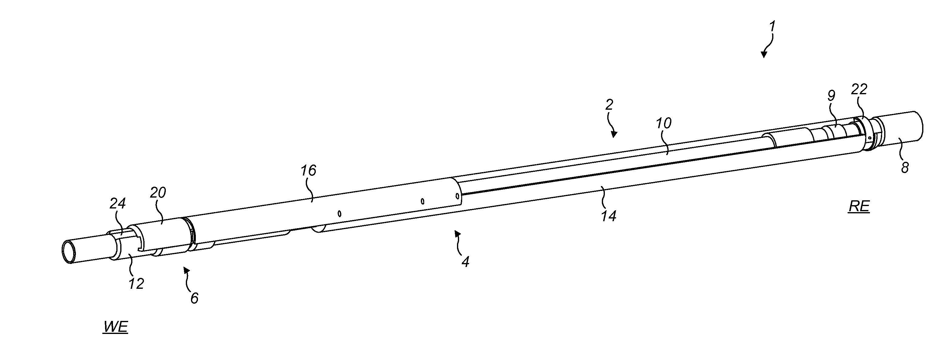
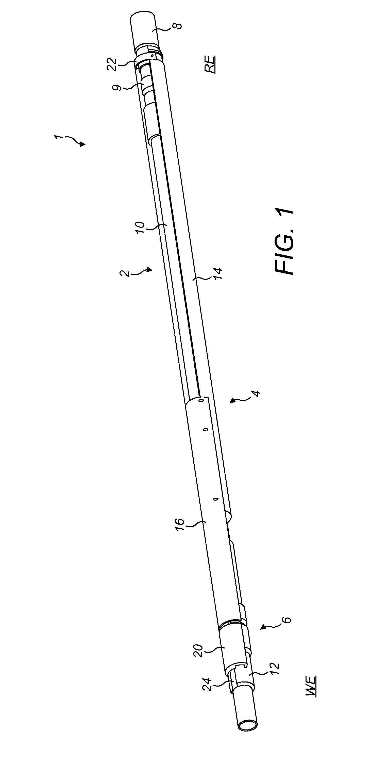
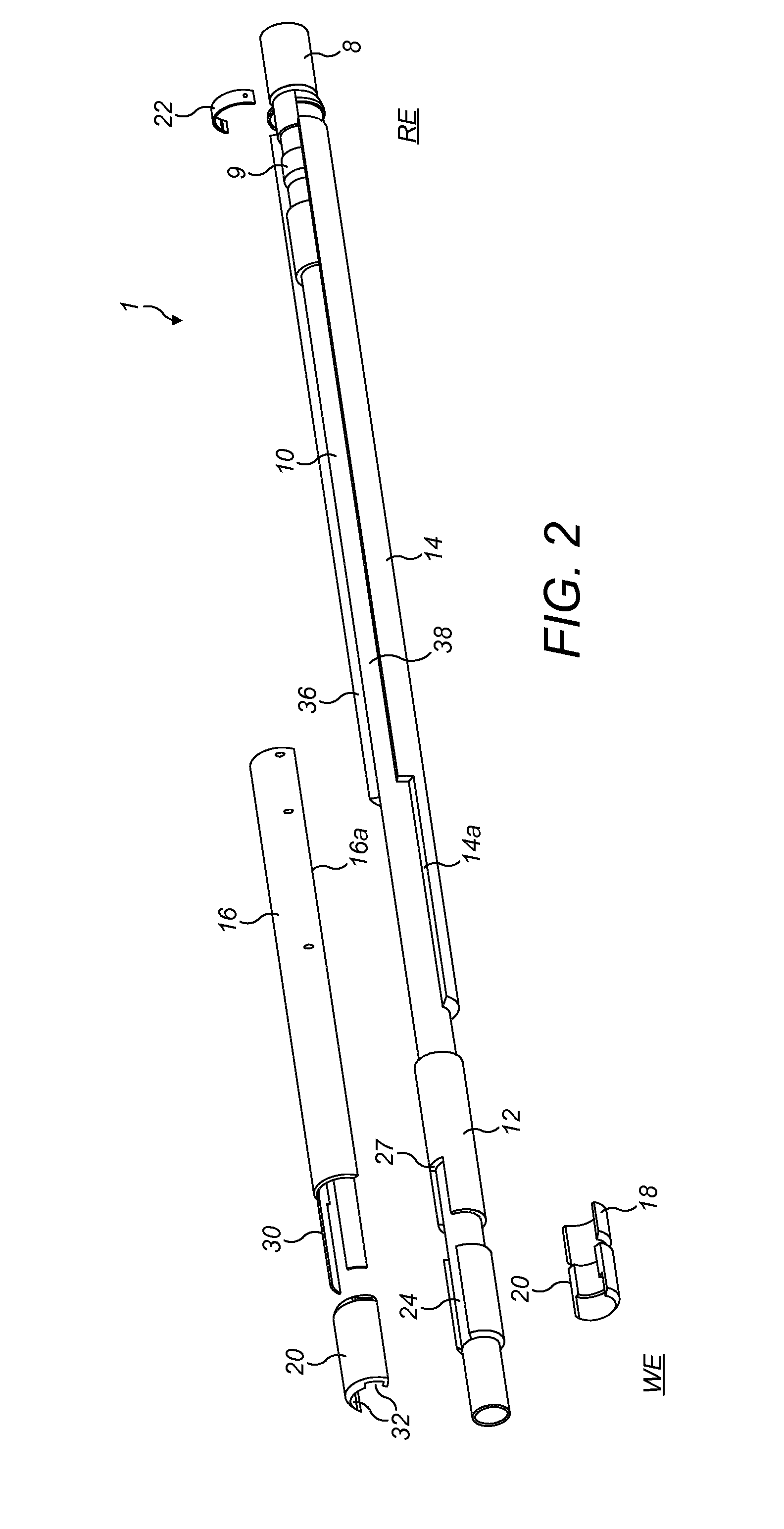
There is provided a downhole umbilical release assembly comprising a guillotine arrangement provided by a guillotine alignment sub (12) and a guillotine mandrel (16). The guillotine alignment sub has a first edge (27) over which an umbilical is positioned in a wellbore string. The guillotine mandrel is positioned radially outwardly of the guillotine alignment sub and is arranged to move longitudinally with respect thereto. The guillotine mandrel has a second edge (29) that is arranged to pass over the first edge (27) of the guillotine alignment sub during longitudinal movement of the guillotine mandrel relative to the guillotine alignment sub. This severs an umbilical positioned between the two edges (27,29).

Description

TECHNICAL FIELD[0001]The invention relates to an apparatus for releasing a downhole umbilical, and to a corresponding method of releasing a downhole umbilical.INTRODUCTION[0002]Under some circumstances, for example during work-over of an oil and gas well, cutting and retrieval of the drilling or production tubing may be required. In many wells, in particular those on the Norwegian Continental Shelf (NCS), downhole umbilicals (e.g., control lines) are hooked up to downhole equipment for power supply, communication between surface and a downhole control unit, and / or for monitoring the equipment downhole. If it is necessary to cut and retrieve part of the drilling or production string it is also necessary to cut the umbilicals. While the cutting location on the tubing is well defined, it is difficult to control where the umbilical is cut. Excess umbilical left in the wellbore above the production tubing cut may hinder later operations downhole, for example towards the borehole assembly...

Claims


Application Information

Patent Timeline
IPC IPC(8): E21B29/04E21B29/06
CPCE21B29/06E21B29/04E21B29/08
Inventor SORBO, ESPENLOFTHUS, TOMMY
Owner OIL TOOLS OF NORWAY
Why Eureka
Try Eureka