Intelligent Control Wave Energy Power Generating System

a power generation system and intelligent control technology, applied in the direction of electric generator control, passive/reactive control, machines/engines, etc., can solve the problems of inability too fragile to use in real wave conditions, and unpredictable wave directions

Active Publication Date: 2016-05-19
LEE MICHAEL FUQUAN
View PDF23 Cites 9 Cited by
  • Summary
  • Abstract
  • Description
  • Claims
  • Application Information

AI Technical Summary

Benefits of technology

[0029]FIG. 8 is a schematic view of an embodiment of a power plant with ten intelligent control wave energy power generating systems in accordance with the present invention;
[0030]FIG. 9 is a schematic illustration of a control mechanism of the intelligent control wave energy power generating system in FIG. 1C;
[0031]FIG. 10 is a schematic illustration demonstrating th

Problems solved by technology

However, these apparatuses usually have three limitations.
First, they are too fragile to use in real wave conditions.
Wave directions are usually unpredictable.
Variations of wave direction will cause unpredictable motion of the gearing assembly, which will result in extra wear and even breakage of the gearing assembly.
Second, these apparatuses are inefficient in converting wave energy into electric energy.
A substantial energy loss occurs each time the entire floating assembly is uplifted by wave action, leaving less energy for driving the gearing

Method used


Image

  • Intelligent Control Wave Energy Power Generating System
  • Intelligent Control Wave Energy Power Generating System
  • Intelligent Control Wave Energy Power Generating System

Examples


Embodiment Construction

[0033]In the following description, for the purposes of explanation, numerous specific details are set forth in order to provide a thorough understanding of the present invention. It is apparent, however, to one skilled in the art that the present invention may be practiced without these specific details or with an equivalent arrangement. Embodiments of the present invention are described herein with reference to illustrations of idealized embodiments. As such, variations from the shapes of the illustrations as a result, for example, of manufacturing techniques and / or tolerances, are to be expected. There is no intent to limit the principles of the present invention to the particular disclosed embodiments. For example, in the drawings, the size and relative sizes of layers and regions may be exaggerated for clarity. In addition, embodiments of the present invention should not be construed as limited to the particular shapes of regions illustrated herein but are to include deviations...


PUM


Abstract

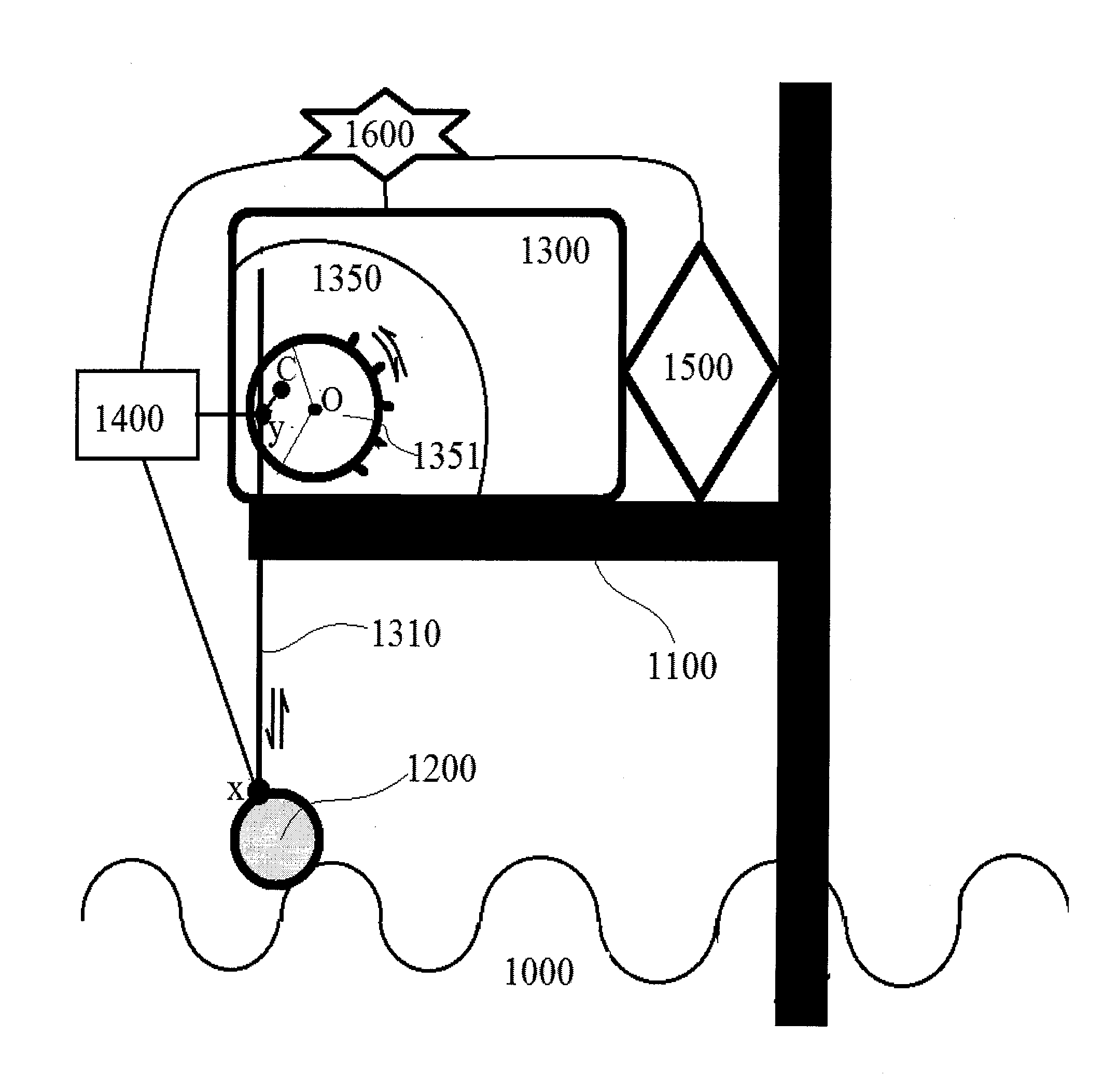
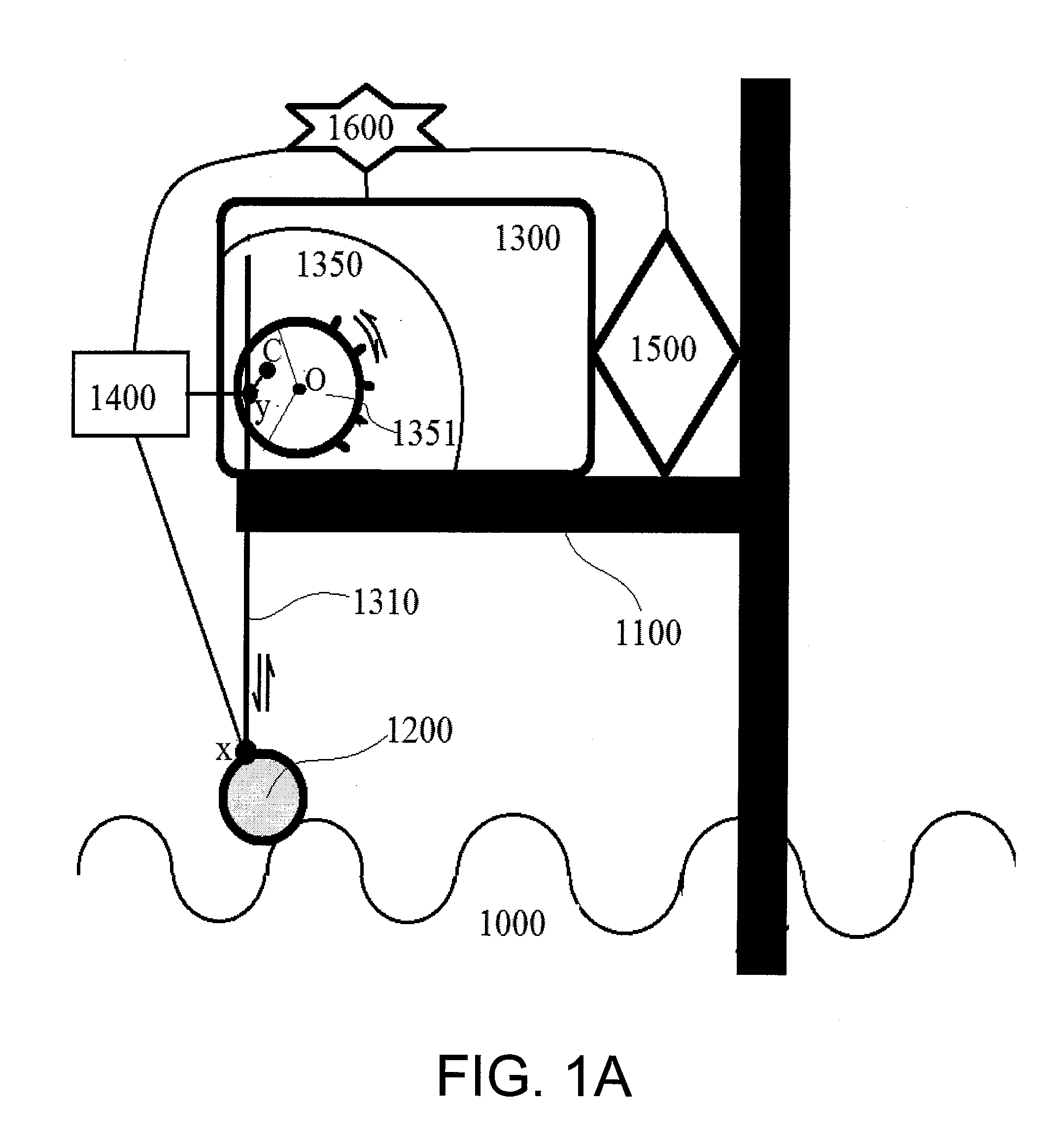
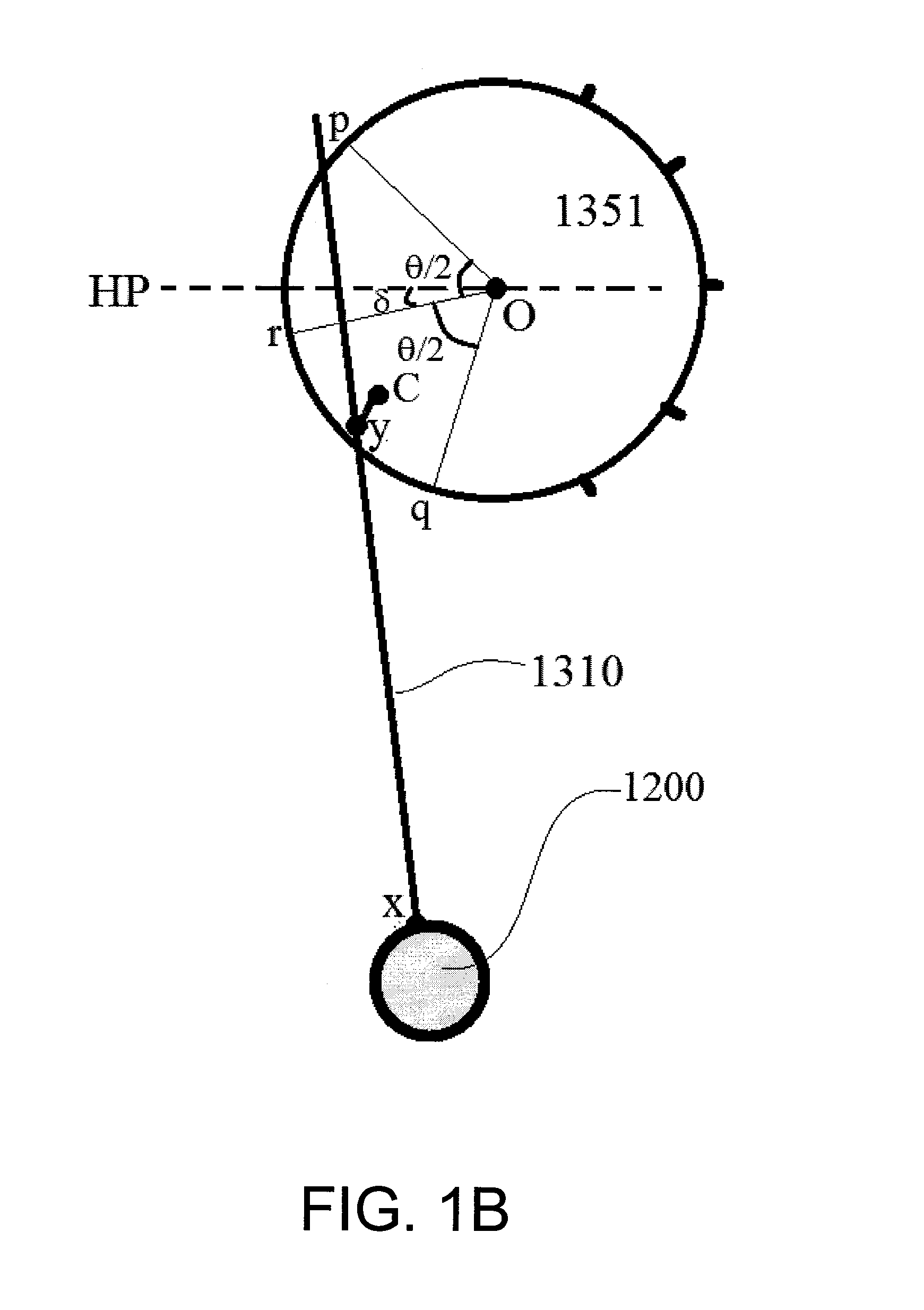
The present invention provides a system and method for converting wave energy into electric energy in an intelligent, practical, and efficient manner. The system utilizes a power input shaft coupled with a vertically reciprocating buoy to rotate a crank gear and a ratchet gear meshing therewith. An intelligent control system is included to monitor, control, and optimize the operations of the system. The length of the power input shaft is adjusted in response to water level fluctuations so that the rotational motion of the crank gear is intelligently controlled within a predetermined desirable region for maximum efficiency.

Description

CROSS-REFERENCE TO RELATED U.S. APPLICATIONS[0001]This application is a CIP application of U.S. application Ser. No. 13 / 700,471 to Michael Fuquan Lee, filed on Jun. 8, 2011, and titled “Intelligent Control Wave Energy Power Generating System”, which is a 371 of PCT / US11 / 39532 filed Jun. 8, 2011, which claims priority from U.S. Provisional Patent Application No. 61 / 397,257 to Michael Fuquan Lee, filed on Jun. 9, 2010, and titled “Wave Energy Power Plant”. The contents of these applications are incorporated herein by reference in their entirety.STATEMENT REGARDING FEDERALLY SPONSORED RESEARCH OR DEVELOPMENT[0002]Not applicable.NAMES OF PARTIES TO A JOINT RESEARCH AGREEMENT[0003]Not applicable.REFERENCE TO AN APPENDIX SUBMITTED ON COMPACT DISC[0004]Not applicable.FIELD OF THE INVENTION[0005]The present invention generally relates to a power generating system utilizing wave energy. More particularly, the vertical motion of a buoy on waving water is translated into the rotational motion ...

Claims


Application Information

Patent Timeline
IPC IPC(8): F03B13/18
CPCF03B13/186F03B13/1855F03B15/00F05B2260/4031F05B2270/107F05B2270/402F05B2270/602F05B2270/80Y02E10/30
Inventor LEE, MICHAEL FUQUAN
Owner LEE MICHAEL FUQUAN
Why Eureka
Try Eureka