Method of determining the magnitude of a field variable of an energy wave

a field variable and energy wave technology, applied in the field of simulating wave propagation, can solve the problems of computational cost, difficulty in distinguishing boundaries from defects in the model, and difficulty in direct determining wave propagation through a medium having complex boundaries in accordance with physical laws

Active Publication Date: 2016-05-19
ROLLS ROYCE PLC
View PDF1 Cites 1 Cited by
  • Summary
  • Abstract
  • Description
  • Claims
  • Application Information

AI Technical Summary

Benefits of technology

[0025]Advantageously, the method provides a method of simulating whether a defect can be detected by reflecting an energy wave from a defect, for a defect in a given location in a modelled domain of interest. Consequently, the method can be used to prove that any defects within the modelled domain of interest are detectable, thereby ensuring that defects do not go undetected during acceptance testing.

Problems solved by technology

However, directly determining wave propagation through a medium having complex boundaries in accordance with physical laws is computationally expensive.
However, in known methods, singularities (i.e. errors in the computation) occur at boundaries as well as at defect areas, making it difficult to distinguish boundaries from defects in the model.
In each case however, there is a compromise between wave propagation simulation accuracy and computational expense, as more accuracy generally leads to longer computational time required to carry out the calculation.
However, while faster, such geometrical methods are less accurate.

Method used


Image

  • Method of determining the magnitude of a field variable of an energy wave
  • Method of determining the magnitude of a field variable of an energy wave
  • Method of determining the magnitude of a field variable of an energy wave

Examples


Embodiment Construction

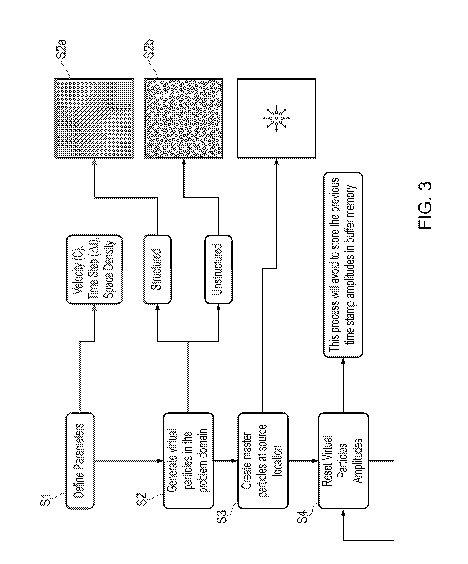
[0033]FIG. 3 shows steps in a method of determining the magnitude of a field variable of an energy wave propagating through a medium with respect to time in accordance with the present disclosure. Example results of this simulation are shown in FIGS. 4a to 4c.

[0034]In a first step S1, parameters of the process are defined. These parameters include the velocity of the energy wave in question in the simulated medium (for example, the speed of sound c in the medium where the wave is a sound wave), as well as the initial amplitude of the wave, and the initial wavelength of the energy wave. Where the medium is anisotropic (i.e. the speed of sound c is dependent on the direction of travel), this parameter may comprise a direction dependent function. Further parameters include a desired temporal resolution (i.e. the difference in time At between time steps) and spatial resolution of master and virtual particles (which will be explained in greater detail hereafter).

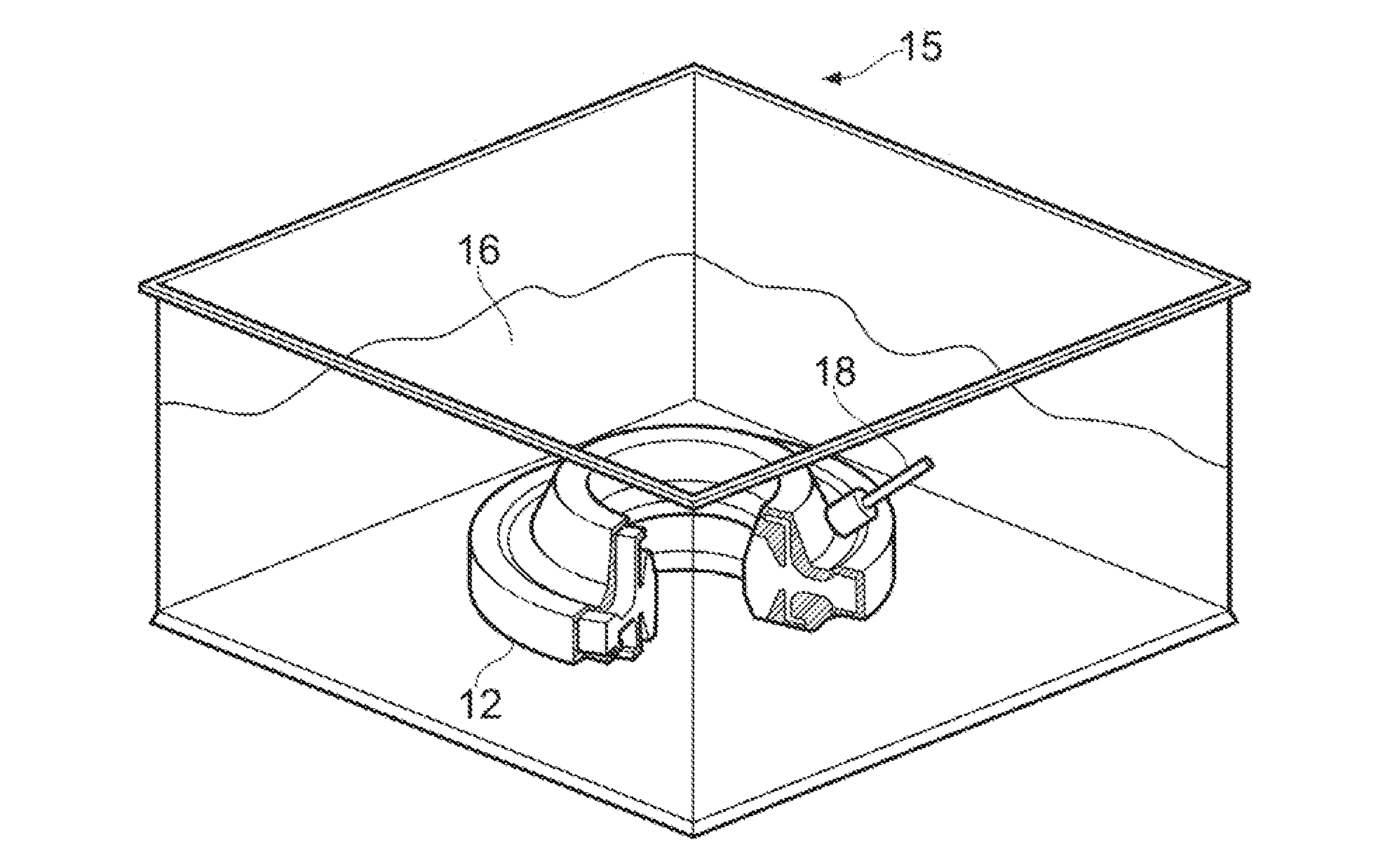
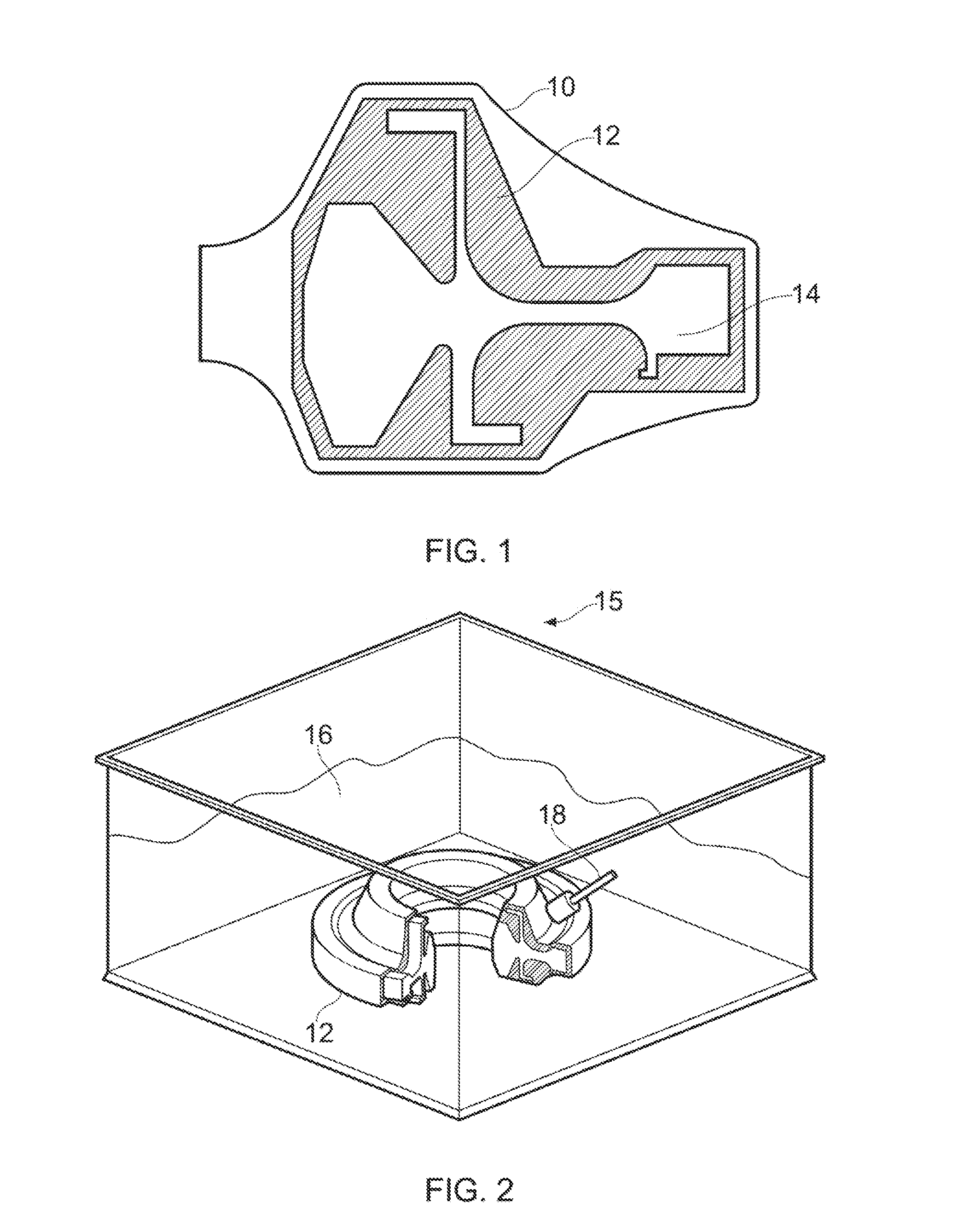
[0035]In step S2, a prob...


PUM

PropertyMeasurementUnit
distanceaaaaaaaaaa
energyaaaaaaaaaa
lengthaaaaaaaaaa

Abstract

Determining magnitude of a field variable of an energy wave through domain of interest, including steps of: defining plurality of master-particles spaced within domain, master-particles being representative of field variables of energy wave at location of respective master-particle, and defining supporting domain Ωm for each master-particle; computing field variables including position, magnitude and direction of propagation of each master-particle at predetermined time; defining plurality of virtual-particles within domain representative of magnitude of field variable of wave at location of respective virtual-particle; calculating magnitude uv of field variable of each virtual-particle at time of interest by applying formula:uv=∑m=1Numf(q1)×g(q2)Wherev∈Ωmwhere N is total number of master-particles, um is magnitude of respective master-particle, f(q1) is an envelope function relating magnitude of virtual-particle to distance from master-particle in direction of propagation of master-particle, and g(q2) is a smoothing function relating magnitude of virtual-particle to distance from master-particle normal to direction of propagation of master-particle.

Description

FIELD OF THE INVENTION[0001]The present invention relates to a method of simulating wave propagation in a medium, and particularly but not exclusively to a method of simulating ultrasound propagation through a candidate metallic preform shape to determine whether the metallic preform shape is inspectable by ultrasonic testing.BACKGROUND TO THE INVENTION[0002]Waves such as electromagnetic, seismic and acoustic waves propagate through media in a predictable way in accordance with well understood physical principles. However, directly determining wave propagation through a medium having complex boundaries in accordance with physical laws is computationally expensive.[0003]In one example, it may be desirable to perform non-destructive testing (NDT) in the form of ultrasonic testing on a workpiece to ensure that no defects such as inclusions are present in the raw material prior to carrying out further machining. FIG. 1 shows a cross sectional view through part of a forging 10 for a turb...

Claims


Application Information

Patent Timeline
Patent Type & Authority Applications(United States)
IPC IPC(8): G01N29/44G01N29/04
CPCG01N29/4472G01N29/041G01N2291/0423G01N2291/0422G01N2291/0289
Inventor SEETHAPATHY, MANITAMMINENI, SREE VAMSIWISEALL, STEPHEN SAMUELWRIGHT, DAVID CAMERONCHAPMAN, CRAIG BRIANRAJU, PATHMESWARAN
Owner ROLLS ROYCE PLC
Why Eureka
Try Eureka