Transcatheter mitral valve

a transcatheter, mitral valve technology, applied in the field of heart valve system, can solve the problems of significant valvular dysfunction, left and volume overload of left ventricular, and achieve the effect of improving the quality of life and reducing the risk of ventricular dilation and dysfunction

Active Publication Date: 2016-05-26
RGT UNIV OF CALIFORNIA
View PDF17 Cites 72 Cited by
  • Summary
  • Abstract
  • Description
  • Claims
  • Application Information

AI Technical Summary

Benefits of technology

[0017]Further, the frame is configurable between a collapsed configuration and an open configuration, such the collapsed configuration allows the transcatheter mitral valve to be delivered into position against a native mitral valve annulus and upon expanding to the open configuration, the transcatheter mitral valve is secured in place by the fixture.

Problems solved by technology

Proper valve function depends on the interaction of all of the anatomic components and a minor dyssynchrony can result in significant valvular dysfunction.
With the deranged valvular structure and / or function permitting back / low there is a resultant left ventricular volume overload.
Over time and with deterioration of the mitral valve function, this volume overload results in left ventricular dilation and dysfunction.
Left ventricular dysfunction in conjunction with MR can lead to pulmonary hypertension, congestive heart failure and ultimately death.
These statistics illustrate the gravity of this problem and the immense cost burden that it creates.
Finally, in the elderly, annular calcification is a cause of MR, however this rarely progresses past moderate and infrequently requires intervention.
MR is a mechanical problem, thus medical therapy has been shown to be inadequate, and a mechanical intervention (e.g., repair or replacement) is required to improve mortality.
Another controversy within the field of mitral valve repair and replacement is the timing of the intervention.
These factors can be subjective and inaccurate.
This leads to eligible patients being passed over and perhaps some patients having operations unnecessarily.
However, it has been difficult to apply this technology to the mitral valve given its unique anatomical position close to the left ventricular outflow tract.
Thus, development of a percutaneous system for mitral valve replacement has not yet been effectively achieved.
Nevertheless, there exists numerous challenges in the design and fabrication of a percutanously delivered mitral valve.
For example, one challenge is the development of a system that will secure the valve in place and developing a fully functional and durable valve that can be crimped into a catheter.
Placing a stented valve in a non-calcified aortic valve would create a much higher risk for valve embolization.
With respect to percutaneous delivery, there are not any currently ongoing clinical trials evaluating a percutaneous valve delivery system for the mitral valve diseases.
The mitral valve position presents unique challenges for the placement of a transcatheter valve, including, but not limited to inherent anatomic features of the mitral valve (MV) that make fixation and perivalvular seal with currently available devices a challenge, the lack of a calcium bed to fix the valve, and challenges in delivery catheter size due to the increased annulus diameter of the mitral when compared to the aortic valve.
Destruction of the mitral valve apparatus at the tune of mitral valve replacement causes an immediate decrease in chamber contractility and an increase in afterload as the radius term in the Laplace equation increases.

Method used


Image

  • Transcatheter mitral valve
  • Transcatheter mitral valve
  • Transcatheter mitral valve

Examples


Embodiment Construction

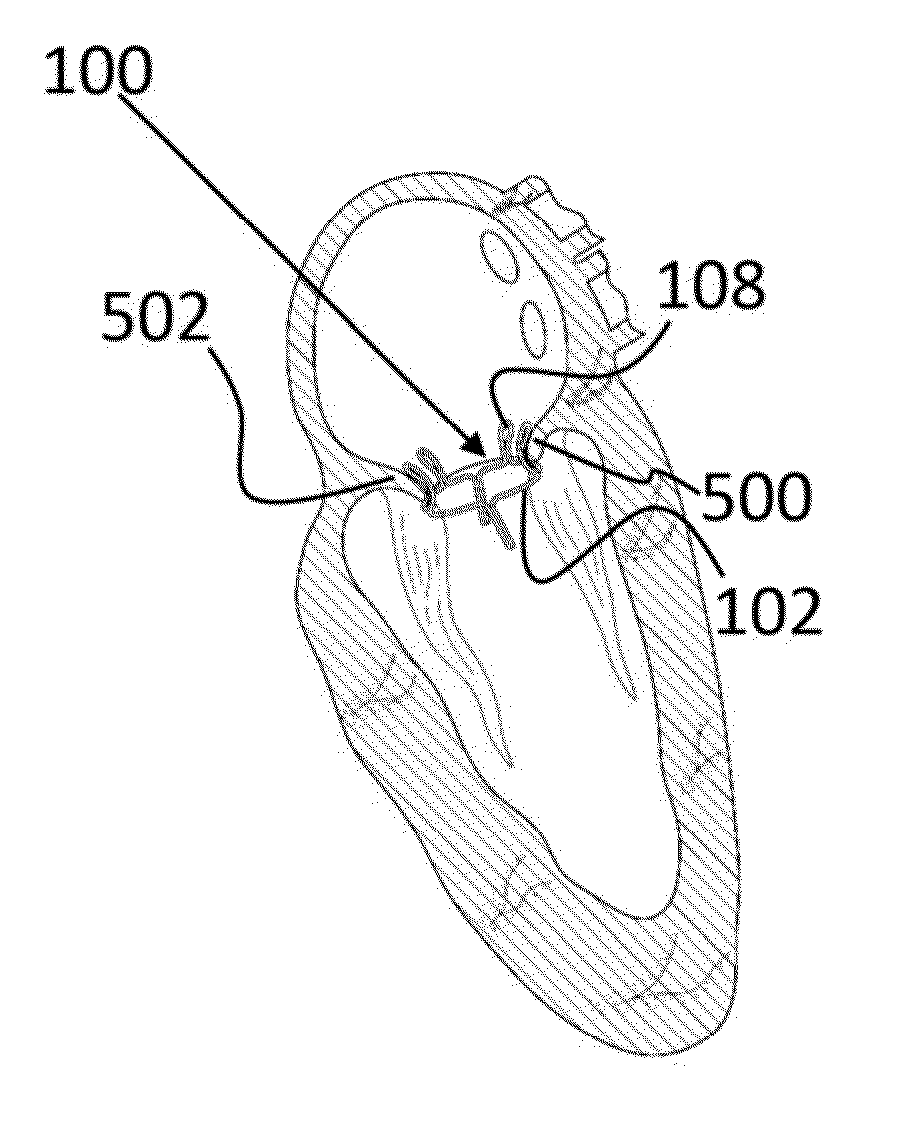
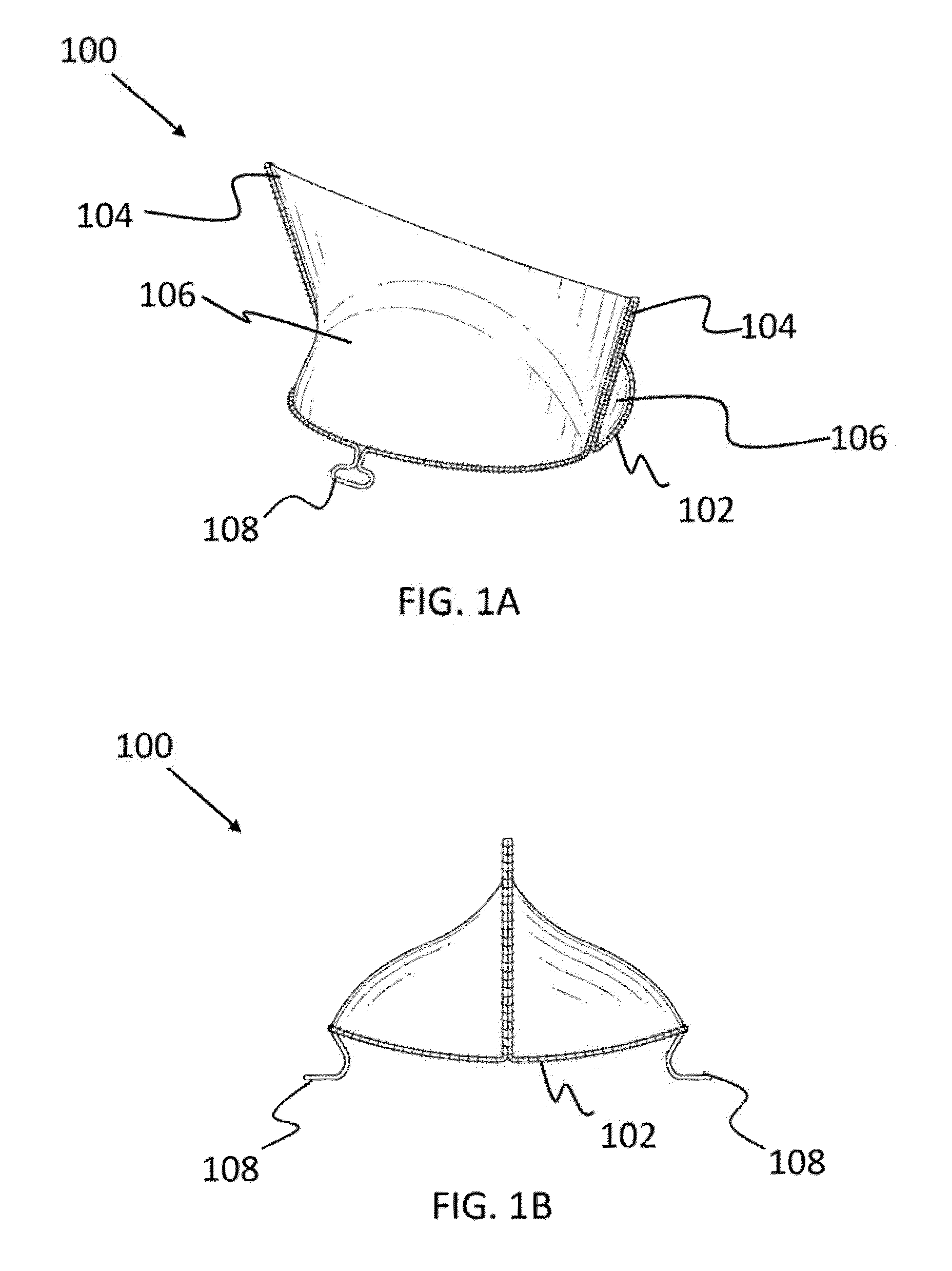
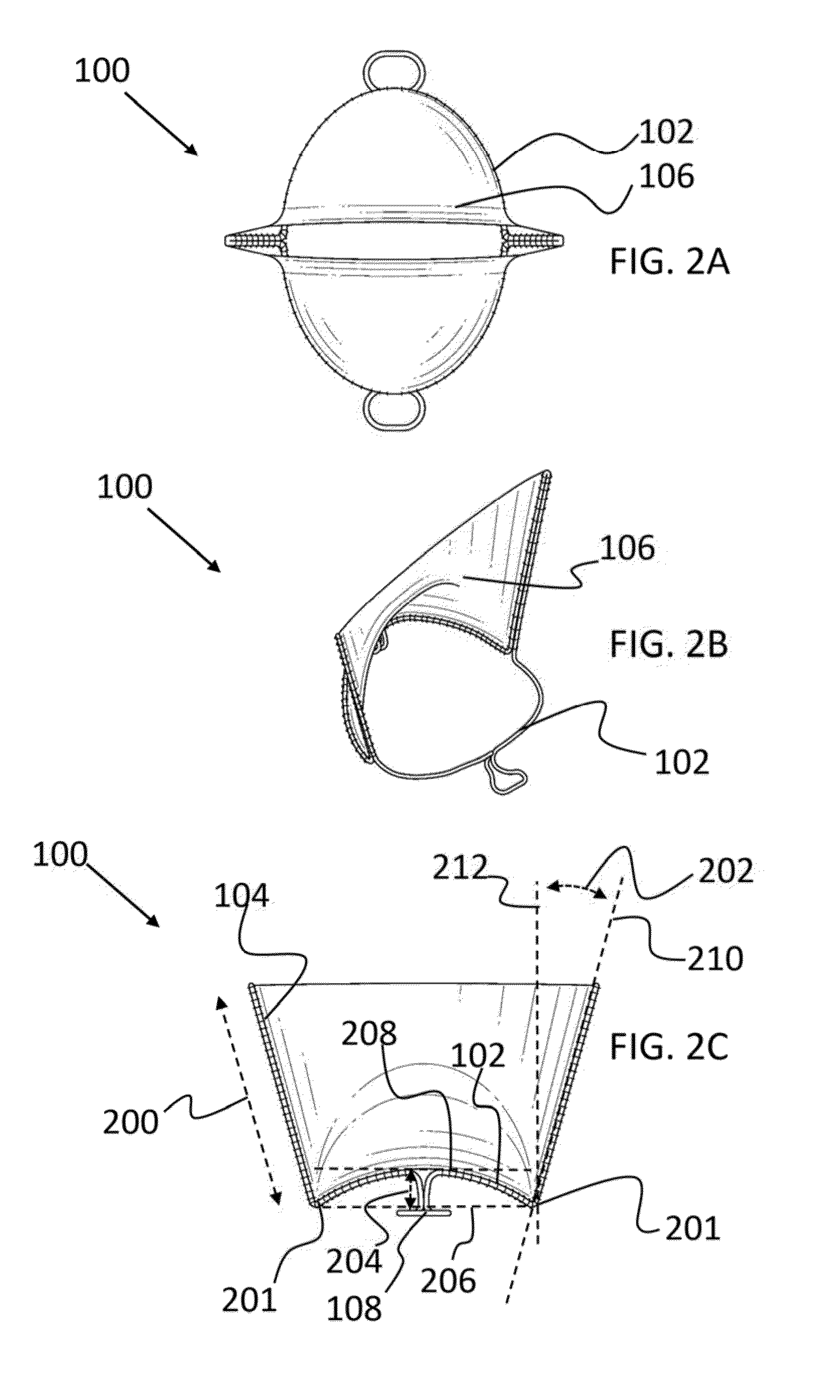
[0048]The present invention relates to a heart valve system and, more particularly, to a percutaneous mitral valve for delivery and implantation at a mitral position. The following description is presented to enable one of ordinary skill in the art to make and use the invention and to incorporate it in the context of particular applications. Various modifications, as well as a variety of uses in different applications will be readily apparent to those skilled in the art, and the general principles defined herein may be applied to a wide range of embodiments. Thus, the present invention is not intended to be limited to the embodiments presented, but is to be accorded the widest scope consistent with the principles and novel features disclosed herein.

[0049]In the following detailed description, numerous specific details are set forth in order to provide a more thorough understanding of the present invention. However, it will be apparent to one skilled in the art that the present inven...


PUM


Abstract

Described is a transcatheter mitral valve. The mitral valve includes a saddle-shaped annulus frame with two prongs extending therefrom. Two leaflets are attached with the frame and prongs to form a bi-leaflet mitral valve. The frame is collapsible to a collapsed configuration that allows for delivery and implantation at a mitral position. When at the mitral position, the mitral valve expands into an open configuration and is secured in place by a fixture, such as clamps that extend from the frame.

Description

CROSS-REFERENCE TO RELATED APPLICATIONS[0001]This is a Continuation-in-Part application of U.S. patent application Ser. No. 14 / 221,194, entitled, “Percutaneous Heart Valve Delivery Systems,” filed on Mar. 20, 2014. This is ALSO a Non-Provisional Utility Patent Application of U.S. Provisional Application No. 61 / 835,083, filed on Jun. 14, 2013, entitled, “Collapsible Mitral Valve for Percutaneous Delivery and Implantation.”BACKGROUND OF THE INVENTION[0002](1) Field of Invention[0003]The present invention relates to a heart valve system and, more particularly, to a percutaneous mitral valve for delivery and implantation at a mitral position.[0004](2) Description of Related Art[0005]Valvular heart disease is the third most common cause of cardiovascular disease in the United States. Mitral Regurgitation (MR) is a common valvular disorder, which can be manifested, in acute and chronic forms Both the acute and chronic forms of MR are the source of a significant amount of cardiovascular mo...

Claims


Application Information

Patent Timeline
Patent Type & Authority Applications(United States)
IPC IPC(8): A61F2/24
CPCA61F2/2403A61F2/2412A61B90/37A61B2090/3782A61F2/2418A61F2230/0095
Inventor KHERADVAR, ARASH
Owner RGT UNIV OF CALIFORNIA
Why Eureka
Try Eureka