Control system for exercise machine

a control system and exercise machine technology, applied in computer control, gymnastics exercise, instruments, etc., can solve the problem that the non-inertial system is not the best resistance mod

Inactive Publication Date: 2016-05-26
SCLAFANI ADAM C +1
View PDF4 Cites 9 Cited by
  • Summary
  • Abstract
  • Description
  • Claims
  • Application Information

AI Technical Summary

Benefits of technology

[0019]Another embodiment of the disclosure is to employ interactive software to control the exercise machine. The exercise device becomes interactive, automatic and networked. For example, the software runs on a table or smartphone and interacts with the exercise machine. The user e

Problems solved by technology

While it is marketed as a benefit a non-inertial system is not the best mode of resistance

Method used


Image

  • Control system for exercise machine
  • Control system for exercise machine
  • Control system for exercise machine

Examples


Embodiment Construction

[0026]The system relates to exercise machines. More particularly, it relates to a control system for exercise machines which uses an adjustable tank and a computerized controller.

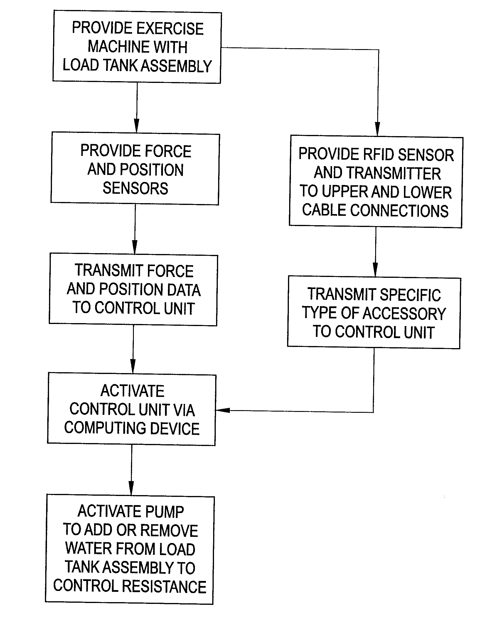
[0027]The basic control system of the present disclosure includes water tanks, a force / weight sensor and pumps. It is manually controlled by the user to increase or decrease the weight in the tank. With the addition of a position sensor and a microcontroller, many additional features become possible. The control system has a user interface that activates the various control programs.

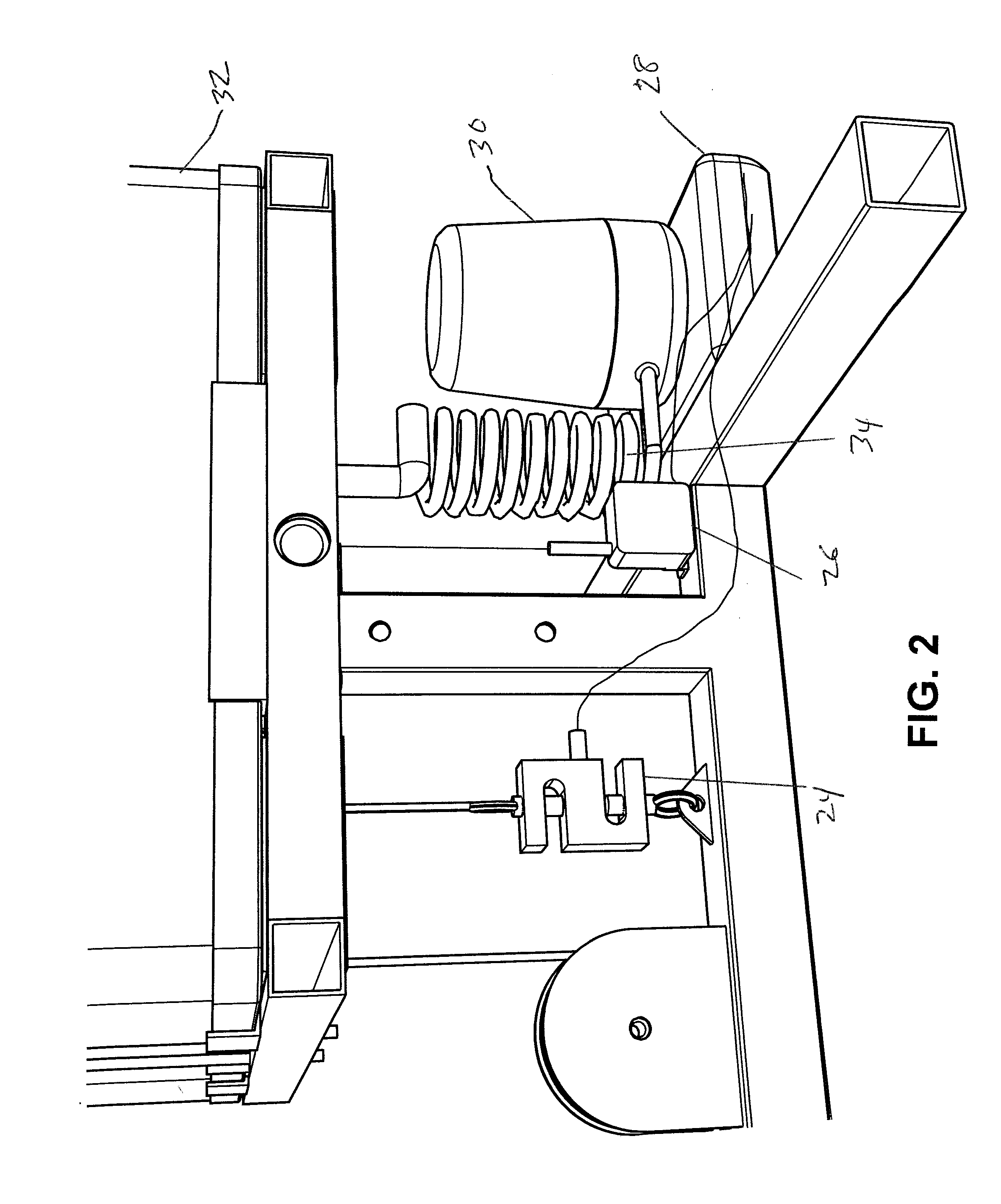
[0028]Specifically, a position sensor 26 can be added to an exercise machine to report data on the motion of the weight tank. This can be used to assess the range of motion, velocity (average and max), acceleration (average and max) of the weight tank and be translated into user performance data. A force sensor 24 is used to assess the amount of force exerted to move the weight and the position sensor 26 can feed data to a micro...


PUM


Abstract

A control system for use with an exercise machine having a first sensor for transmitting force data, a second sensor for transmitting position data, a control unit for receiving the force data and the position data and a pump activated by the control unit to add or remove liquid from a tank to increase or decrease weight resistance for the exercise machine.

Description

CLAIM OF PRIORITY[0001]This application claims priority from Provisional Application Ser. No. 62 / 082,778 filed on Nov. 21, 2014, the entirety of which is hereby incorporated by reference.BACKGROUND OF THE DISCLOSURE[0002]Most common exercise devices incorporate a stack of metal plates connected by various cable and lever mechanisms to an interface appropriate for upper body or lower body exercises. The user selects a desired amount of weight resistance by positioning a pin in the weight stack. The weight stack can vary in total amount and typically has increments of 5 lbs. or 10 lbs. of weight. Various alternative resistance modes of other exercise machines such as Bowflex® (bending of fiberglass rods), Nitroforce (compression of a pneumatic piston), Bowflex® revolution (stretching of elastic elements), etc., affect the manner in which the exercise is performed or the way it feels to the user.[0003]Existing systems are typically non-inertial. While it is marketed as a benefit a non-...

Claims


Application Information

Patent Timeline
IPC IPC(8): A63B24/00F04D27/00A63B21/06G05B15/02
CPCA63B24/0087G05B15/02A63B2024/0093A63B21/0602F04D27/00A63B21/00076A63B21/0603A63B21/154A63B23/03525A63B23/03566A63B23/1218A63B24/0075A63B71/0622A63B2024/0078A63B2071/0081A63B2071/0636A63B2071/065A63B2071/0677A63B2071/068A63B2071/0683A63B2220/13A63B2220/17A63B2220/30A63B2220/40A63B2220/52A63B2225/093A63B2225/15A63B2225/20A63B2225/305A63B2225/50A63B2225/54A63B21/4035A63B21/4043
Inventor SCLAFANI, ADAM C.SCLAFANI, PHILIP K.
Owner SCLAFANI ADAM C
Why Eureka
Try Eureka