Vertical alignment liquid crystal display and manufacture method thereof

Active Publication Date: 2016-05-26
TCL CHINA STAR OPTOELECTRONICS TECH CO LTD
View PDF3 Cites 7 Cited by
  • Summary
  • Abstract
  • Description
  • Claims
  • Application Information

AI Technical Summary

Benefits of technology

[0059]The benefits of the present invention are: the present invention provides a vertical alignment liquid crystal display, and the liquid crystal layer comprises liquid crystal molecules, auxiliary alignment agent and a polymer network penetrating the entire liquid crystal layer, and with the auxiliary alignment agent, the vertical alignment of the liquid crystal molecules can be achieved. The polymer network has an extremely large surface area, and an extremely large contact area with the liquid crystal molecules to stabilize alignment of the liquid crystal molecules and enhance vertical alignment effect of the auxiliary alignment agent to the liquid crystal molecules. Thus, the weaker alignment ability issue of the small molecule auxiliary alignment agent can be solved to enhance the aligning force and the anchoring energy of the auxiliary alignment agent to the liquid crystal molecules and vertical alignment effect of the auxiliary alignment agent to the liquid crystal molecules; the p

Problems solved by technology

However, for realizing the VA alignment, the vertical alignment agent has to be coated on the substrate surface and high temperature baking process has to implement.
Because the alignment agent contains a large amount of NMP solvent, Thus, the alignment layer formation process is a high energy consumptive, extremely non-environmental protective and human body harmful procedure; besides, due to the problems of non-uniformity, lack coating, non-st

Method used


Image

  • Vertical alignment liquid crystal display and manufacture method thereof
  • Vertical alignment liquid crystal display and manufacture method thereof
  • Vertical alignment liquid crystal display and manufacture method thereof

Examples


Example

[0071]For better explaining the technical solution and the effect of the present invention, the present invention will be further described in detail with the accompanying drawings and the specific embodiments.

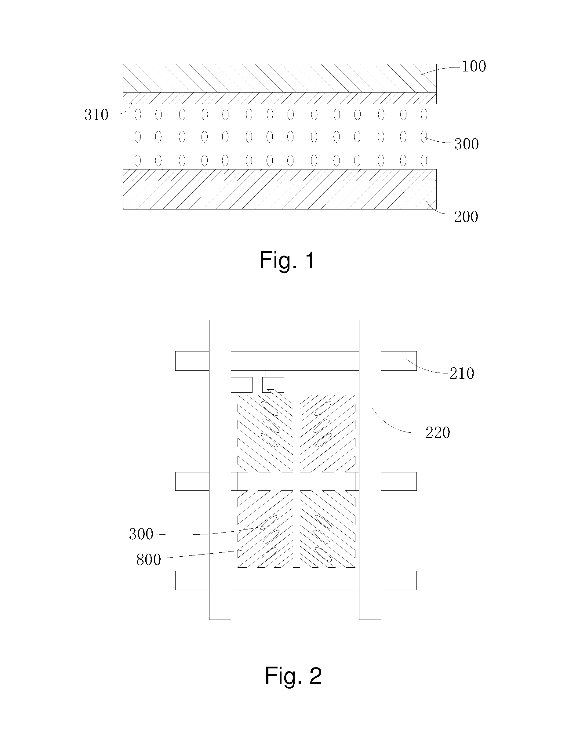
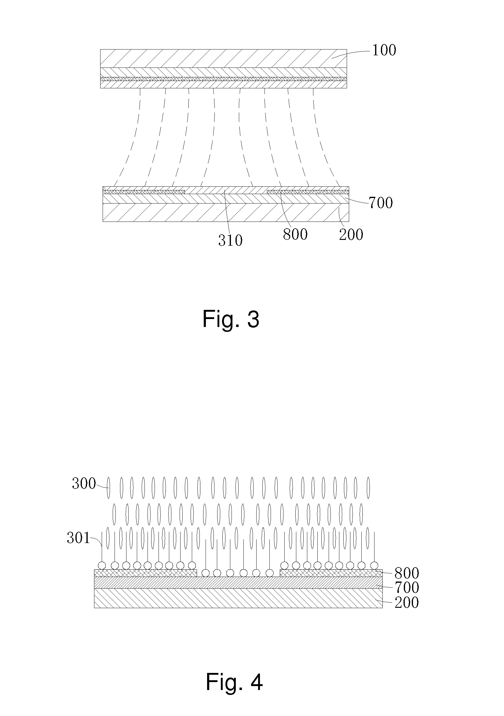
[0072]Please refer to FIG. 5, the present invention first provides a vertical alignment liquid crystal display, comprising a first substrate 1, a second substrate 2, oppositely located with the first substrate 1, a liquid crystal layer 3 located between the first substrate 1 and the second substrate 2, a first passivation layer 11 and a second passivation layer 21 respectively located at inner sides of the first substrate 1 and the second substrate 2 and a common electrode layer 12 and a pixel electrode layer 22 respectively located on the first passivation layer 11 and the second passivation layer 21.

[0073]The first substrate 1 comprises a black matrix, a color filter and photo spacers but not limited thereto. The first substrate 1 is equivalent to a CF substrate of the tradi...


PUM

PropertyMeasurementUnit
Fractionaaaaaaaaaa
Fractionaaaaaaaaaa
Fractionaaaaaaaaaa

Abstract

The present invention provides a vertical alignment liquid crystal display and a manufacture method thereof. The vertical alignment liquid crystal display comprises a first substrate (1), a second substrate (2), a liquid crystal layer (3) located between the first substrate (1) and the second substrate (2), a first and a second passivation layers (11, 21) respectively located at inner sides of the first and the second substrates (1, 2), a common electrode layer (12) and a pixel electrode layer (22) respectively located on the first and the second passivation layers (11, 21); the liquid crystal layer (3) comprises liquid crystal molecules (30), auxiliary alignment agent (31) and a polymer network (33) penetrating the entire liquid crystal layer (3); the auxiliary alignment agent (31) makes the liquid crystal molecules (30) in the liquid crystal layer (3) vertically aligned on the surfaces of the first and the second substrates (1, 2); the polymer network (33) stabilizes alignment of the liquid crystal molecules (30) and enhances vertical alignment effect of the auxiliary alignment agent (31) to the liquid crystal molecules (30).

Description

FIELD OF THE INVENTION[0001]The present invention relates to a display technology field, and more particularly to a vertical alignment liquid crystal display and a manufacture method thereof.BACKGROUND OF THE INVENTION[0002]The LCD (Liquid Crystal Display) possesses many advantages of being ultra thin, power saved and radiation free. It has been widely utilized in, such as LCD TVs, mobile phones, PDAs, digital cameras, laptop screens or notebook screens.[0003]For the TFT-LCD panels in the present main market, three types can be illustrated, which respectively are Twisted Nematic / Super Twisted Nematic (TN / STN), In-Plane Switching (IPS) and Vertical Alignment (VA). The VA liquid crystal display possesses extremely high contrast than the liquid crystal displays of other types, which can reach up to 4000-8000 in general. It has very wide application in large scale display, such as television or etc.[0004]The reason why the VA liquid crystal display possesses extremely high contrast is t...

Claims


Application Information

Patent Timeline
IPC IPC(8): C09K19/56C09K19/54G02F1/1341G02F1/1337G02F1/1334
CPCC09K19/56G02F1/133788G02F1/1334C09K2019/546C09K19/542G02F2001/133742G02F2001/13345G02F1/1341G02F1/1337G02F1/137G02F1/139G02F1/13712C09K19/3028C09K2019/0448C09K2019/2078C09K2019/548G02F1/1393G02F1/13345G02F1/133742G02F1/13775C09K2323/02
Inventor ZHONG, XINHUILEE, YUNGJUI
Owner TCL CHINA STAR OPTOELECTRONICS TECH CO LTD
Why Eureka
Try Eureka