Working vehicle and control method therefor

a technology for working vehicles and control methods, applied in hybrid vehicles, servomotors, instruments, etc., can solve the problems of difficult stably controlling the discharge flow rate of hydraulic pumps, the discharge pressure of hydraulic pumps is not stable, and the energy loss at the relief valve is reduced, and the horsepower required from the engine is reduced. , the effect of reducing the energy loss at the relief valv

Active Publication Date: 2016-05-26
KOMATSU LTD
View PDF5 Cites 10 Cited by
  • Summary
  • Abstract
  • Description
  • Claims
  • Application Information

AI Technical Summary

Benefits of technology

[0024]In the control method according to the exemplary embodiment, during relief, the work implement requirement setting unit may set the upper limit of the required flow rate to a prescribed flow rate limit value to thereby reduce the discharge flow rate of the hydraulic pump. Hereby, the energy loss at the relief valve may be reduced. Additionally, the commanded throttle value sent to the engine is determined based on the required traction force. Therefore, when a large amount of drive power is required for the vehicle to run, the required traction force may be set to a large value to maintain a high engine rotation speed regardl

Problems solved by technology

However, the energy from the hydraulic fluid relieved via the relief valve is converted to heat, and therefore that energy is lost.
Despite that, when the discharge flow rate of the hydraulic pump is reduced by reducing the engine rotation speed as with the above described work vehicle, there is a delay because the discharge flow rate of the hydraulic pump tends not to decrease promptly during relief.
Thus, the discharge pressure of the

Method used


Image

  • Working vehicle and control method therefor
  • Working vehicle and control method therefor
  • Working vehicle and control method therefor

Examples


Embodiment Construction

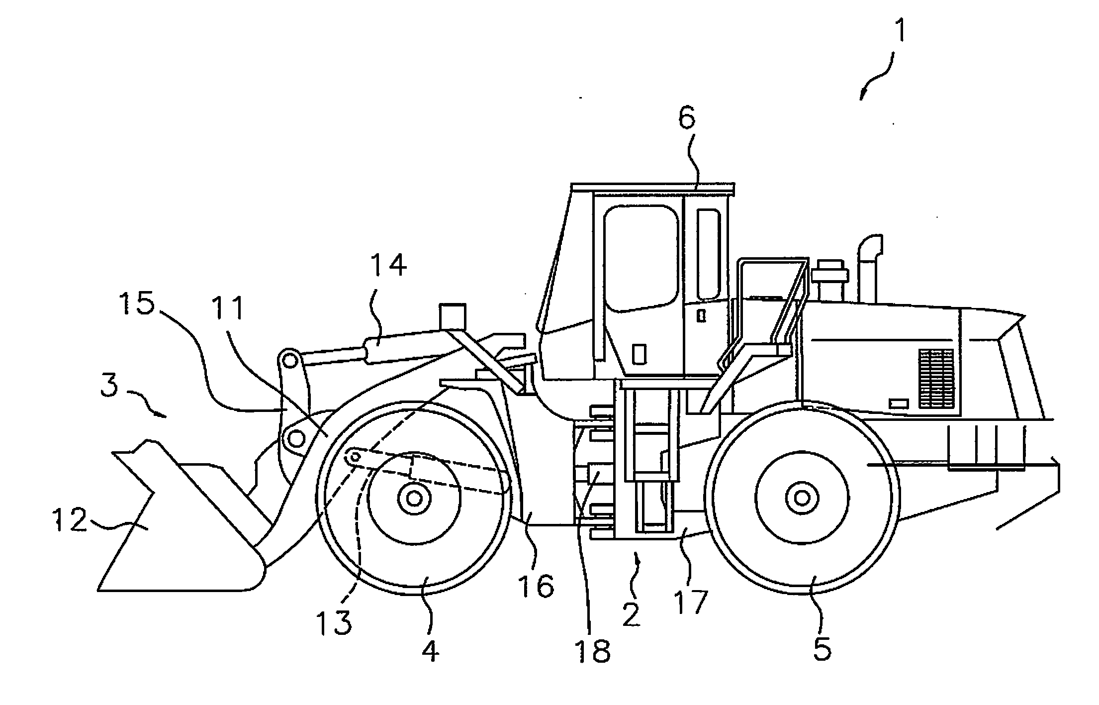
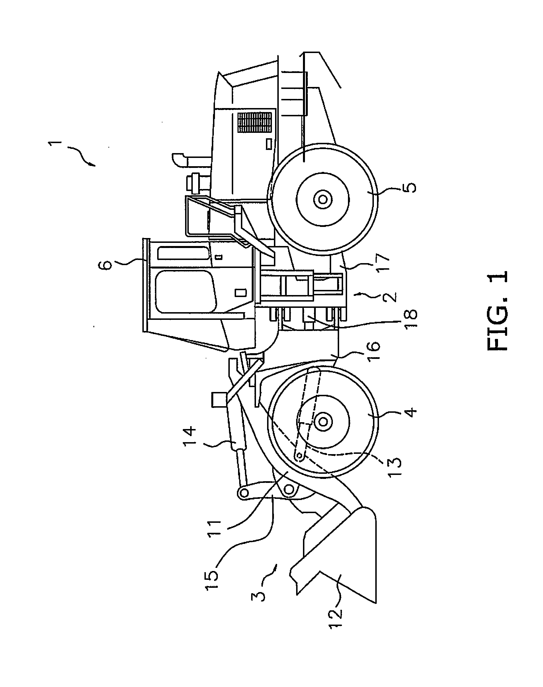
[0042]Exemplary embodiments of the present invention are described below with reference to the drawings. FIG. 1 is a side view illustrating a work vehicle 1 according to an exemplary embodiment of the present invention. As illustrated in FIG. 1 the work vehicle 1 is provided with a vehicle frame 2, a work implement 3, running wheels 4, 5, and a cab 6. The work vehicle 1 is a wheel loader, and travels by rotationally driving the running wheels 4, 5. The work vehicle 1 uses the work implement 3 to perform work, such as excavation or digging.

[0043]The work implement 3 and the running wheels 4, 5 are attached to the vehicle frame 2. The work implement 3 is driven by hydraulic fluid from a later-described work implement pump 23 (refer to FIG. 2). A boom 11 and a bucket 12 are provided on the work implement 3. The boom 11 is mounted to the vehicle frame 2. The work implement 3 is provided with a lift cylinder 13, and a bucket cylinder 14. The lift cylinder 13 and the bucket cylinder 14 ar...


PUM


Abstract

A transmission requirement setting unit sets a required traction force in a work vehicle on the basis of an accelerator operation amount. A work implement requirement setting unit sets a required flow rate on the basis of a work implement operation amount. An engine requirement setting unit determines the horsepower required from the engine on the basis of the horsepower required by the transmission set on the basis of the required traction force, and the horsepower required by the work implement set on the basis of the required flow rate. A required throttle setting unit determines a commanded throttle value sent to the engine on the basis of the horsepower required from the engine. A pump displacement setting unit sets a target displacement for the hydraulic pump on the basis of the required flow rate. The work implement requirement setting unit sets an upper limit for the required flow rate to a prescribed flow rate limit value when the discharge pressure of the hydraulic pump is at or above a prescribed pressure threshold.

Description

CROSS-REFERENCE TO RELATED APPLICATIONS[0001]This application is a U.S. National stage application of International Application No. PCT / JP2014 / 082549, filed on Dec. 9, 2014. This U.S. National stage application claims priority under 35 U.S.C. §119(a) to Japanese Patent Application No. 2014-014214, filed in Japan on Jan. 29, 2014, the entire contents of which are hereby incorporated herein by reference.BACKGROUND[0002]1. Field of the Invention[0003]The present invention relates to a work vehicle and a control method therefor.[0004]2. Background Information[0005]Work vehicles are equipped with a relief valve for ensuring the discharge pressure from a hydraulic pump does not become excessive when a large load is applied to the work implement. The relief valve opens when the discharge pressure of the hydraulic pump increases and reaches a prescribed relief pressure. Relieving a portion of the hydraulic fluid discharged from the hydraulic pump thusly prevents excessive increases in the d...

Claims


Application Information

Patent Timeline
IPC IPC(8): E02F9/22E02F9/20E02F3/28
CPCE02F9/2246E02F3/283E02F9/202E02F9/2296E02F9/2235B60K6/445B60K6/387B60W10/06B60W10/30B60W30/1886B60K2006/381E02F9/2066E02F9/2253E02F9/2289E02F9/2292F02D29/06F15B2211/20523F15B2211/20546F15B2211/50518F15B2211/5151F15B2211/6651F15B2211/6652F15B2211/6654Y02T10/62F02D29/00F02D29/04F15B11/02
Inventor YAMADA, KENICHIYOSHIZAWA, MASAO
Owner KOMATSU LTD
Why Eureka
Try Eureka