Fuel lance cooling for a gas turbine with sequential combustion

a technology of sequential combustion and fuel lance cooling, which is applied in the direction of combustion process, turbine/propulsion fuel flow conduit, air transportation, etc., can solve the problems of reducing the overall efficiency of the power plant, high nox emission level, and high life cycle cost, so as to improve the mixing quality, and reduce the effect of pressure loss

Active Publication Date: 2016-05-26
ANSALDO ENERGIA SWITZERLAND AG
View PDF17 Cites 29 Cited by
  • Summary
  • Abstract
  • Description
  • Claims
  • Application Information

AI Technical Summary

Benefits of technology

[0025]According to another embodiment of the invention said means for improving the mixing quality and reducing pressure loss in said sequential combustor comprises a plurality of vortex generators arranged on said streamlined body on both sides at the trailing ed

Problems solved by technology

As a result, there arise high NOx emission levels and high life cycle costs.
This criterion poses challenges in obtaining appropriate distribution of the fuel across the burner exit area.
The cross flow injection concept used in the current SEV-fuel injection devices (SE

Method used


Image

  • Fuel lance cooling for a gas turbine with sequential combustion
  • Fuel lance cooling for a gas turbine with sequential combustion
  • Fuel lance cooling for a gas turbine with sequential combustion

Examples


Embodiment Construction

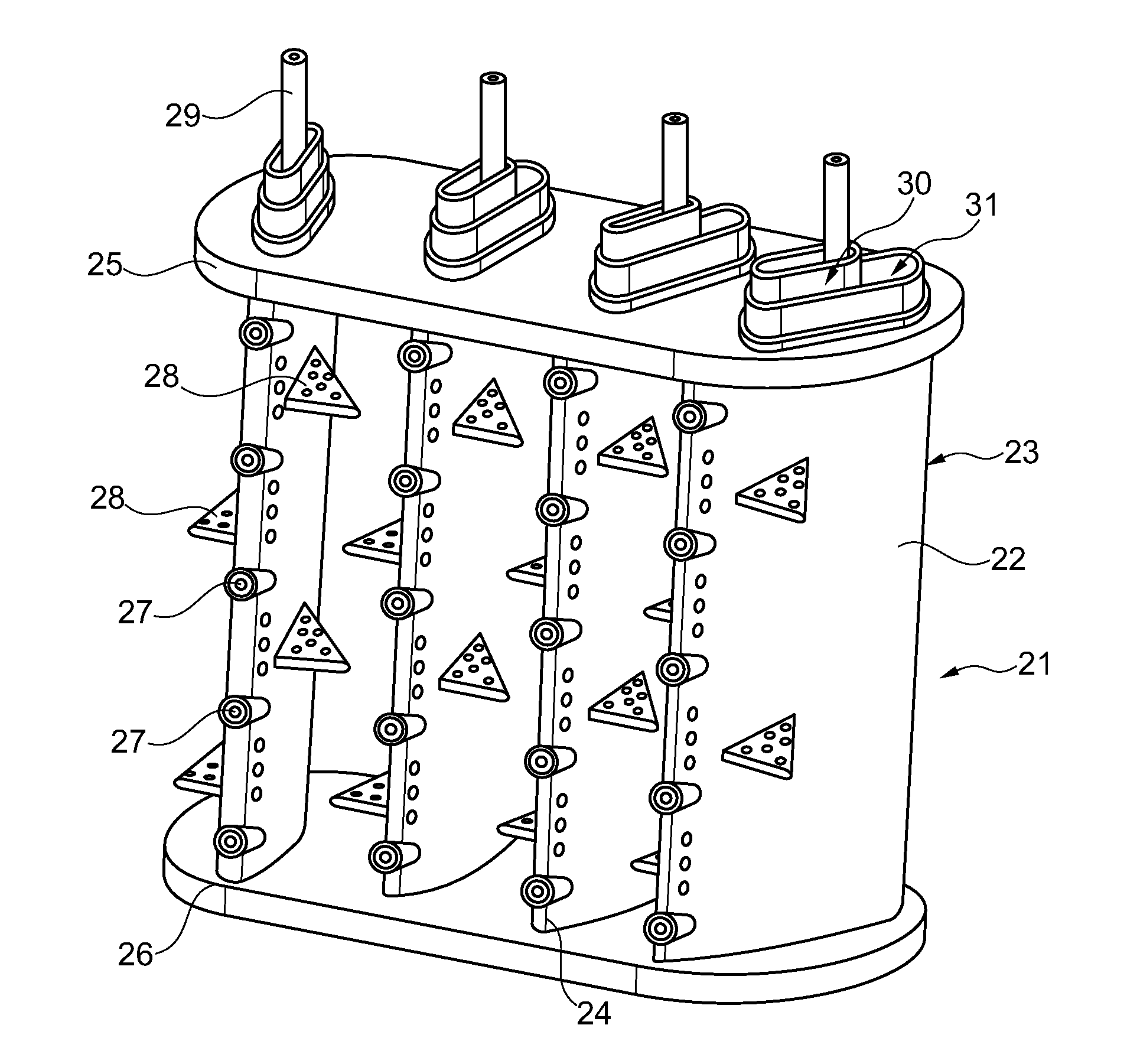
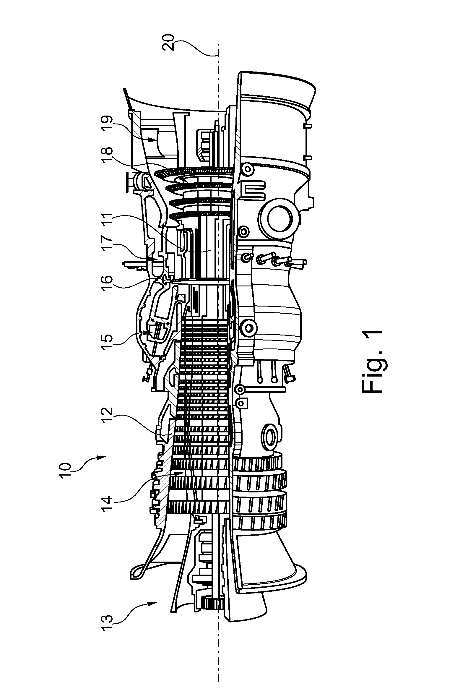
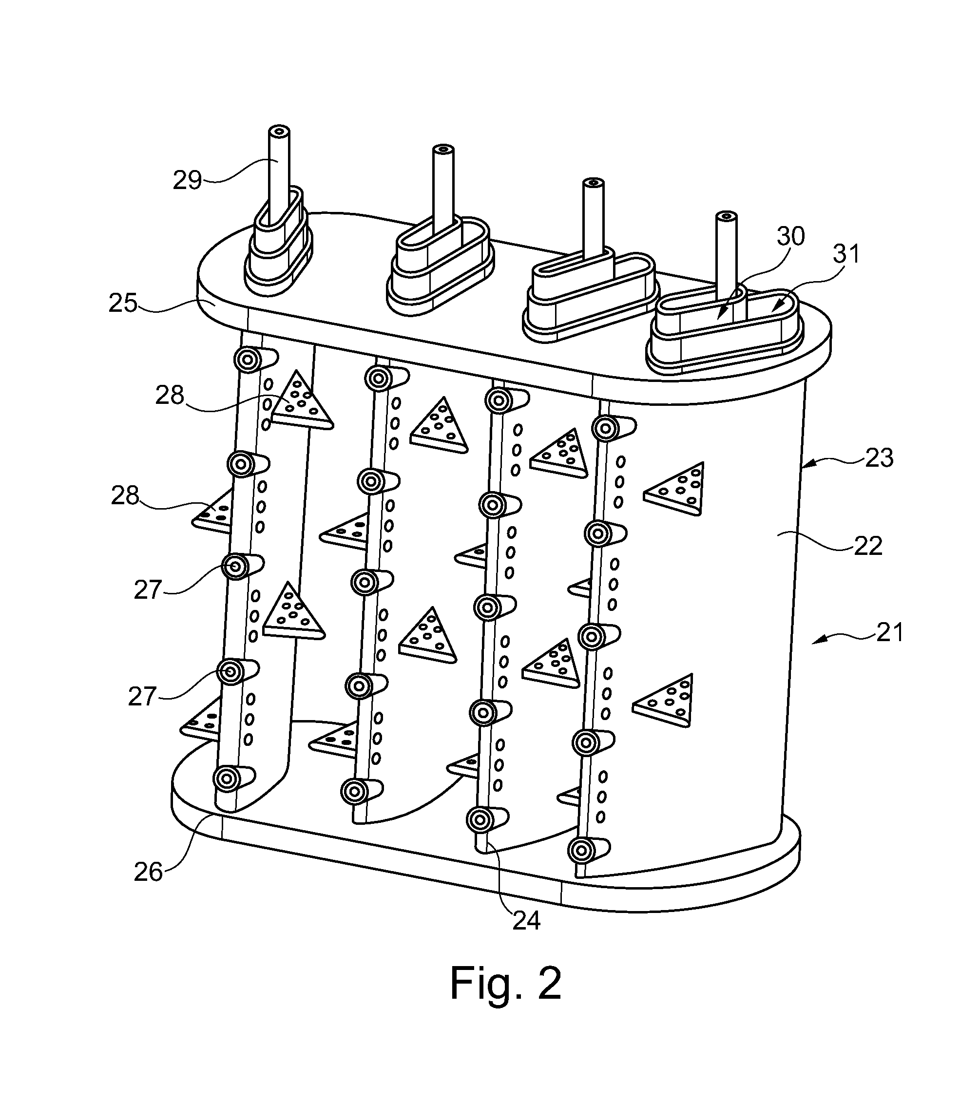
[0052]The constant pressure sequential combustion consists of two combustors (see FIG. 1 of the gas turbine GT26). Implementation of the sequential combustors improves combustion performance and operation flexibility.

[0053]However, there are still problems to improve series cooling systems in sequential burners with impingement cooling, convective cooling and effusion cooling for a complicated structure with fuel gas and fuel oil plenum included. It is thus a desire to achieve optimized cooling, good mixing with hot gas flow and a required lifetime with minimal cooling air for lances used in these burners.

[0054]A VG lance concept was already developed to improve the mixing quality and reduce the SEV pressure loss and further adapted to a VG lance development for a rectangular burner and for a center-body burner. The same was done for a lobe lance for a rectangular burner and for a center-body burner.

[0055]According to the present invention the internal structure and cooling system o...


PUM


Abstract

A fuel lance is disclosed for injecting a gaseous and/or liquid fuel mixed with air into an axial hot gas flow flowing through a sequential combustor of a gas turbine, the fuel lance having at least one finger extending in a longitudinal direction into the axial hot gas flow of the gas turbine essentially perpendicular to the hot gas flow. The finger is configured as a streamlined body which has a streamlined cross-sectional profile. The body has two lateral surfaces essentially parallel to the axial hot gas flow. The body includes an enclosing outer wall having a longitudinally extending air plenum for the distributed introduction of air into the at least one finger. The air plenum is provided with a plurality of distributed impingement cooling holes, such that air exiting through the impingement cooling holes impinges on the inner side of the leading edge region of the body.

Description

BACKGROUND OF THE INVENTION[0001]The present invention relates to the technology of gas turbines with sequential combustion. It refers to a fuel lance cooling according to the preamble of claim 1.PRIOR ART[0002]In order to achieve a high efficiency, a high turbine inlet temperature is required in standard gas turbines. As a result, there arise high NOx emission levels and high life cycle costs. These problems can be mitigated with a sequential combustion cycle, wherein the compressor delivers nearly double the pressure ratio of a conventional one. The main flow passes the first combustion chamber (e.g. using a burner of the general type as disclosed in EP 1 257 809 or as in U.S. Pat. No. 4,932,861, also called EV combustor, where the EV stands for environmental), wherein a part of the fuel is combusted. After expanding at the high-pressure turbine stage, the remaining fuel is added and combusted (e.g. using a burner of the type as disclosed in U.S. Pat. No. 5,431,018 or U.S. Pat. No...

Claims


Application Information

Patent Timeline
IPC IPC(8): F23R3/28F02C7/22
CPCF23R3/283F23R2900/03044F23R2900/03341F02C7/222F23R3/20Y02T50/60F23C7/002F23R3/12F23R3/18F23R3/16F23R3/286
Inventor GAO, XIANFENGBENZ, URSTHEUER, ANDREDUSING, MICHAEL
Owner ANSALDO ENERGIA SWITZERLAND AG
Why Eureka
Try Eureka