Zoom lens and image pickup apparatus including the same

Inactive Publication Date: 2016-05-26
CANON KK
View PDF1 Cites 9 Cited by
  • Summary
  • Abstract
  • Description
  • Claims
  • Application Information

AI Technical Summary

Benefits of technology

The present invention provides a zoom lens that includes three lens units having different refractive powers. During zooming, the second lens unit moves towards the image side and changes the interval between adjacent lens units. The first lens unit has a positive refractive power and includes a positive lens and a negative lens arranged adjacent to each other. The refractive indexes and partial dispersion ratios of the materials used for the lenses are specified to achieve desired optical properties. In addition, a conditional expression is satisfied to achieve desired optical performance. The zoom lens has a compact design and can easily change focal length from a wide angle end to a telephone end.

Problems solved by technology

However, there are cases where a sufficient amount of light cannot be obtained from the near-infrared light, for example, when there is very little moon light around the time of a new moon and when the moon is hidden by a cloud.
In the zoom lens disclosed in Japanese Patent Application Laid-Open No. 2011-053526, the zoom ratio is high, but the aberrations are not sufficiently corrected up to the near-infrared range of a wavelength of 1.6 μm.
In the zoom lenses disclosed in Japanese Patent Application Laid-Open Nos. 2013-88782 and 2013-171207, the axial aberration is favorably corrected from the visible range to the near-infrared range, but the zoom ratio is not sufficiently high.

Method used


Image

  • Zoom lens and image pickup apparatus including the same
  • Zoom lens and image pickup apparatus including the same
  • Zoom lens and image pickup apparatus including the same

Examples


example 1

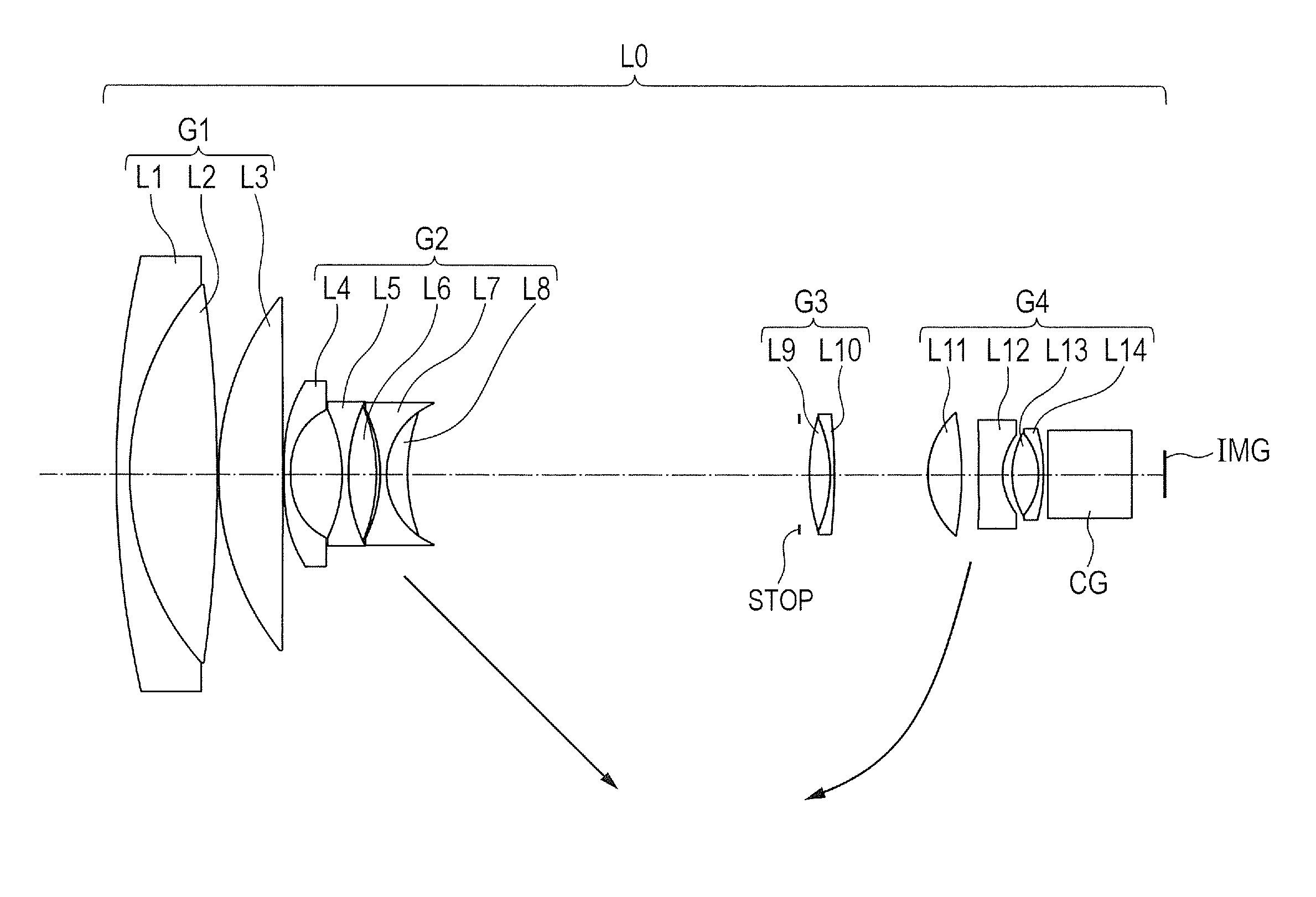
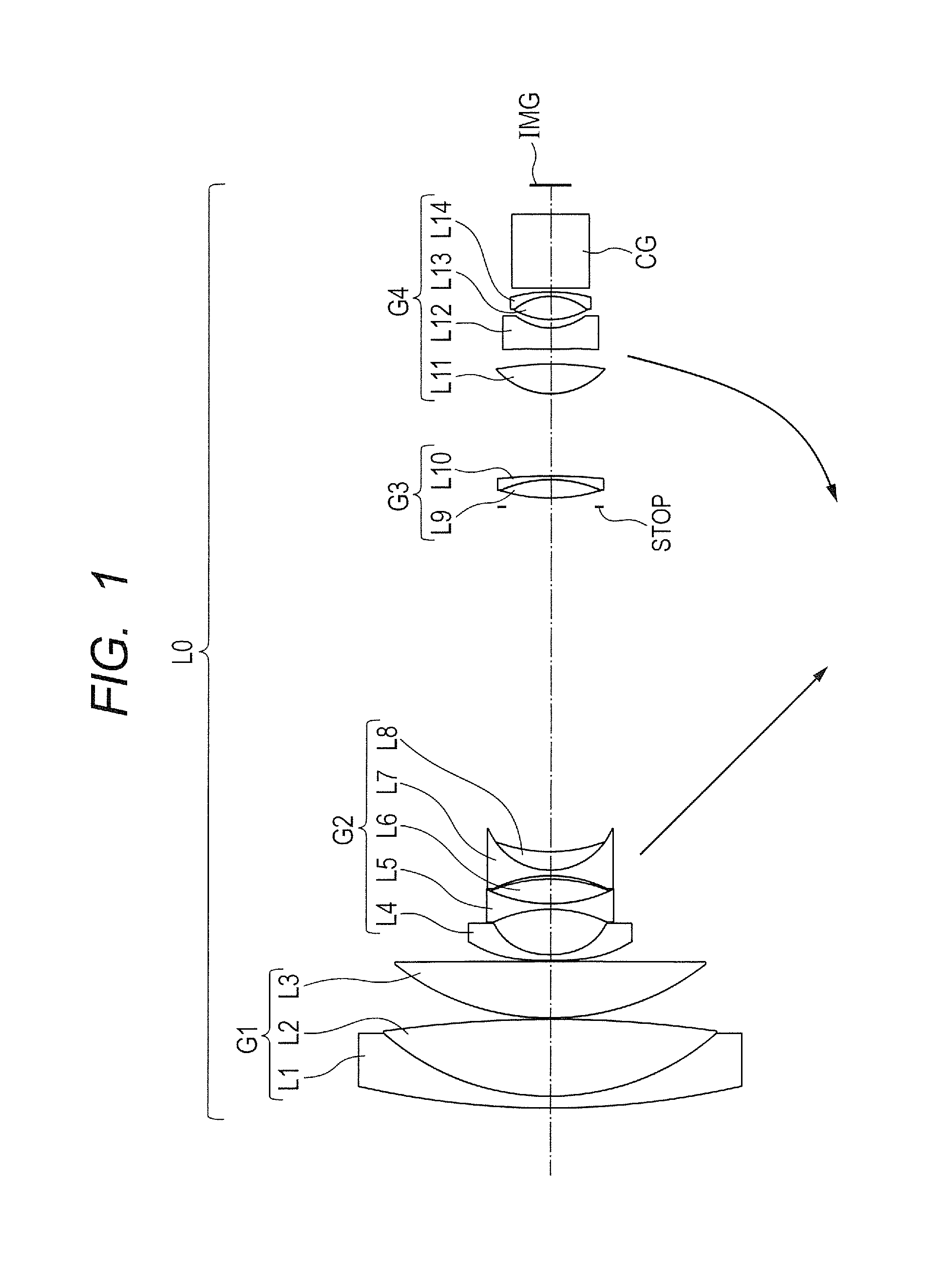
[0069]The structure of the zoom lens of Example 1 is described. The zoom lens of Example 1 includes the first lens unit G1 having a positive refractive power, the second lens unit G2 having a negative refractive power, the aperture stop STOP that determines a predetermined aperture, the third lens unit G3 having a positive refractive power, and the fourth lens unit G4 having a positive refractive power. The optical block CG is arranged between the fourth lens unit G4 and the image plane IMG. If this optical block CG is not necessary, the optical block CG can be omitted. In the following, an i-th lens counted in order from the object side to the image side is represented by Li.

[0070]The first lens unit G1 includes a lens L1 having a negative refractive power (hereinafter referred to as “negative lens”), a lens L2 having a positive refractive power (hereinafter referred to as “positive lens”), and a lens L3 having a positive refractive power, and the negative lens L1 and the positive ...

example 2

[0073]The structure of the zoom lens of Example 2 is described. Example 2 is the same as Example 1 in signs of the refractive powers of the respective lens units, movement of the respective lens units during zooming, and the like.

[0074]The first lens unit G1 includes a negative lens L1, a positive lens L2, a negative lens L3, a positive lens L4, and a positive lens L5. The negative lens L1 and the positive lens L2 are cemented, and the negative lens L3 and the positive lens L4 are cemented. The second lens unit G2 includes a negative lens L6, a negative lens L7, a positive lens L8, a negative lens L9, and a positive lens L10. The negative lens L7 and the positive lens L8 are cemented, and the negative lens L9 and the positive lens L10 are cemented. Aspherical surfaces are used for both surfaces of the negative lens L6.

[0075]The third lens unit G3 includes a positive lens L11 and a negative lens L12. The positive lens L11 and the negative lens L12 are cemented. The fourth lens unit G...

example 3

[0076]The structure of the zoom lens of Example 3 is described. The zoom lens of Example 3 includes the first lens unit G1 having a positive refractive power, the second lens unit G2 having a negative refractive power, the aperture stop STOP that determines a predetermined aperture, and the third lens unit G3 having a positive refractive power. The optical block CG is arranged between the third lens unit G3 and the image plane IMG. If this optical block CG is not necessary, the optical block CG can be omitted.

[0077]The first lens unit G1 includes a negative lens L1, a positive lens L2, a negative lens L3, a positive lens L4, and a positive lens L5. The negative lens L1 and the positive lens L2 are cemented, and the negative lens L3 and the positive lens L4 are cemented. The second lens unit G2 includes a negative lens L6, a negative lens L7, a positive lens L8, a negative lens L9, and a positive lens L10. The negative lens L7 and the positive lens L8 are cemented, and the negative l...


PUM


Abstract

Provided is a zoom lens, comprising, in order from an object side to an image side: a first lens unit having a positive refractive power; a second lens unit having a negative refractive power; and a third lens unit having a positive refractive power. The second lens unit is configured to move toward the image side during zooming from a wide angle end to a telephoto end, and an interval between adjacent lens units is changed during zooming. The first lens unit includes a positive lens and a negative lens that are arranged adjacent to each other. Materials for the positive lens and the negative lens are appropriately set.

Description

BACKGROUND OF THE INVENTION[0001]1. Field of the Invention[0002]The present invention relates to a zoom lens, and more particularly, to a zoom lens suitable as an image pickup optical system to be used in an image pickup apparatus, such as a monitoring camera, a digital camera, a video camera, and a broadcasting camera.[0003]2. Description of the Related Art[0004]In recent years, as an image pickup optical system to be used in an image pickup apparatus, a zoom lens is required to have a high zoom ratio and a small overall system size. For example, as an image pickup optical system for a monitoring camera, a zoom lens is required to have a small overall system size and a high zoom ratio, and is also required that favorable optical characteristics can be obtained in imaging during daytime and at night.[0005]In general, a monitoring camera uses visible light in imaging during daytime, and uses near-infrared light in imaging at night. The use of near-infrared light provides an advantage...

Claims


Application Information

Patent Timeline
IPC IPC(8): G02B15/173G02B13/14G02B15/16
CPCG02B15/173G02B13/146G02B15/16G02B15/144113G02B15/145129
Inventor NAKANO, MASATSUGUKAJIYAMA, KAZUHIKOSAIGA, TAKEYOSHI
Owner CANON KK
Why Eureka
Try Eureka