Eureka AIR delivers breakthrough ideas for toughest innovation challenges, trusted by R&D personnel around the world.

Data transmission system, data transmission monitoring method, and computer-readable medium

Inactive Publication Date: 2016-05-26
VIVOTEK INC
View PDF6 Cites 2 Cited by
  • Summary
  • Abstract
  • Description
  • Claims
  • Application Information

AI Technical Summary

Benefits of technology

This patent describes a system and method for monitoring the quality of data transmitted over a network. The system includes a server device and a client device connected via a network. The server device generates a data stream with a data generation rate and sends it to the client device. The client device compares the data generation rate with the data it receives from the stream. If there is a difference, the client device generates a warning signal to indicate poor transmission quality. This allows the client device to quickly determine the quality of the data and take steps to improve communication quality. The method is efficient and effective in detecting and addressing network transmission quality issues, leading to improved overall data transmission.

Problems solved by technology

In actual applications, a communication jam leading to a failure in operation of an instant messaging application may occur due to an instantaneous huge data on the route or an unstable network node in the route.
When a communication jam occurs, a data receiving terminal cannot receive entire data in time for further processing even though a data source end has sent the data completely.
When a communication jam occurs, except that the data receiving terminal is unable to receive whole data in time, data to be transmitted also heap up, which makes the communication jam worse.
Therefore, the two kinds of transmission mechanisms cannot quickly detect the existence of an unacceptable communication jam for any improvement in communication quality.

Method used


Image

  • Data transmission system, data transmission monitoring method, and computer-readable medium
  • Data transmission system, data transmission monitoring method, and computer-readable medium
  • Data transmission system, data transmission monitoring method, and computer-readable medium

Examples


Embodiment Construction

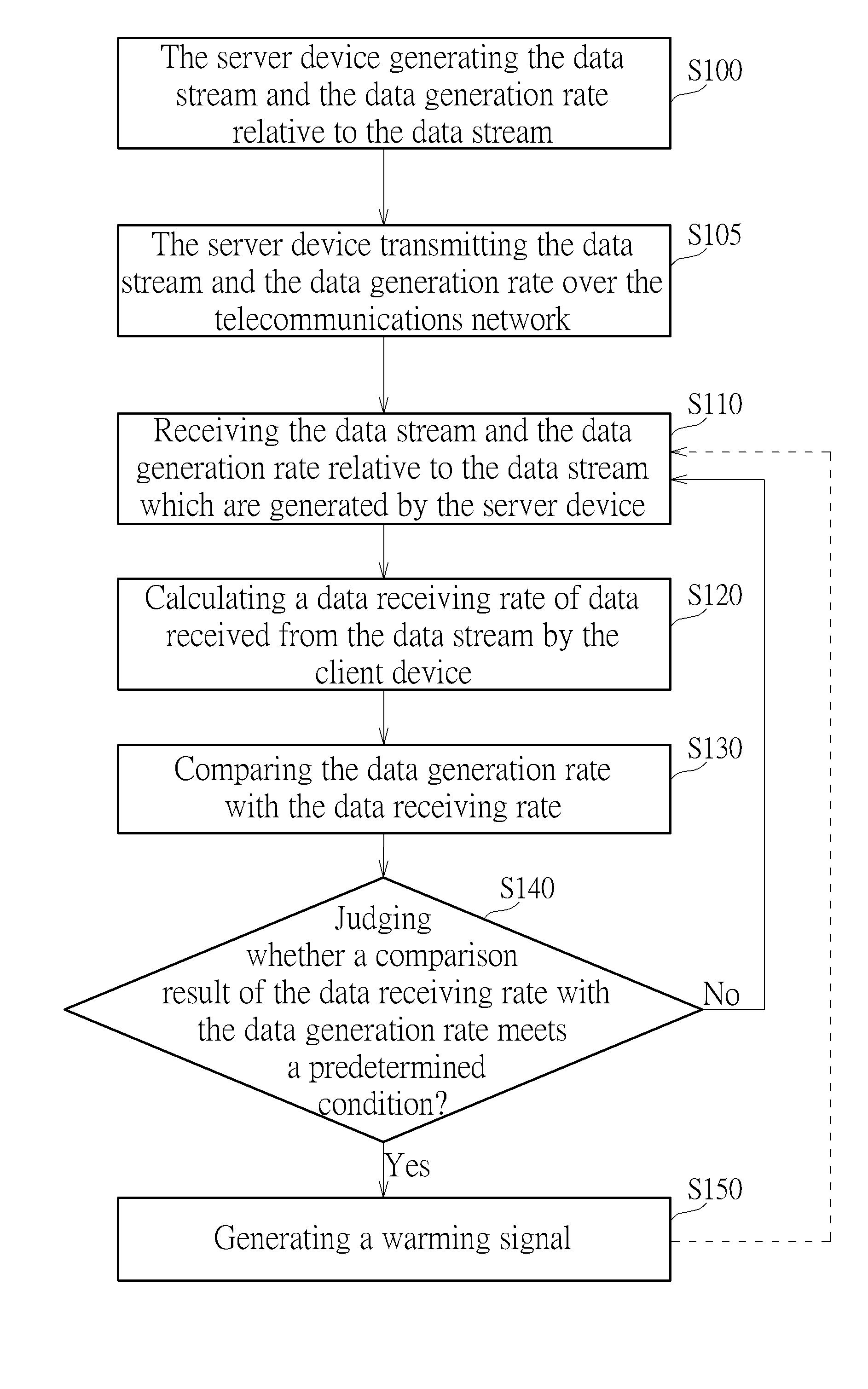
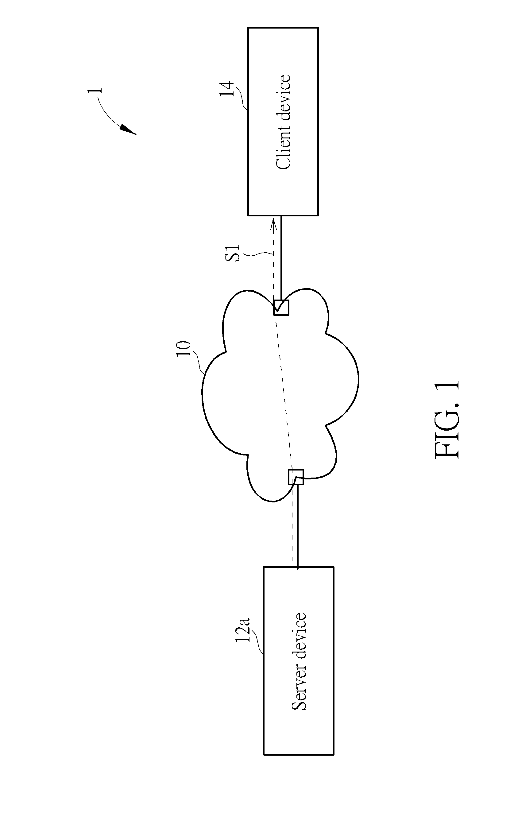
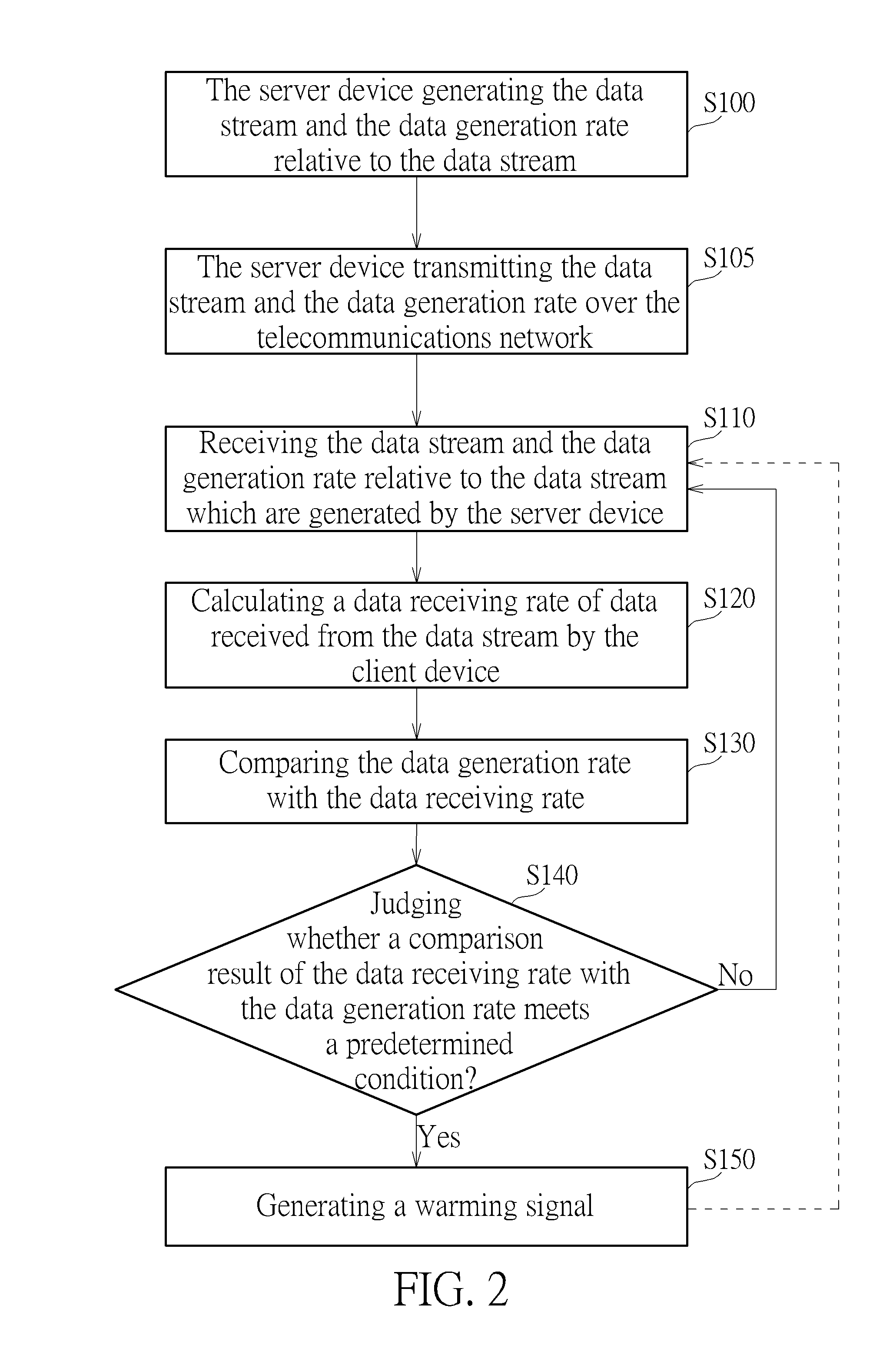
[0018]Please refer to FIG. 1 that is a schematic diagram illustrating a data transmission system 1 of an embodiment according to the invention. The data transmission system 1 includes a server device 12a and a client device 14 which are linked to a telecommunications network 10. Therein, the telecommunications network 10 is not limited to a single network topology or communications technology, and can be a hybrid network in practice. The server device 12a is used for generating a data stream S1 (indicated by a dashed line with an arrow in FIG. 1) and a data generation rate relative to the data stream S1. For example, the data generation rate can be a value of an amount of data, processed into the data stream S1 in a time period, divided by the time period. The server device 12a can transmit the data stream S1 and the data generation rate to the client device 14 over the telecommunications network 10. Therein, the data generation rate can be embedded into the data stream S1 and trans...


PUM


Abstract

A method of monitoring data transmission is applied to a data transmission system which includes at least one server device and a client device, each of which is linked to a telecommunications network. The at least one server device is used for generating a data stream and a data generation rate relative to the data stream. The data stream and the data generation rate are transmitted to the client device over the telecommunications network. The client device calculates a data receiving rate of data received from the data stream by the client device, and determines whether a comparison result of the data receiving rate with the data generation rate meets a predetermined condition. If YES, the client device generates a warming signal.

Description

BACKGROUND OF THE INVENTION[0001]1. Field of the Invention[0002]The invention relates to a data transmission system and a data transmission monitoring method, and especially relates to a system of transmitting data over a telecommunications network and a method thereof.[0003]2. Description of the Prior Art[0004]Various instant messaging applications through computer networks are practicable because of an increasingly wider communication bandwidth. In actual applications, a communication jam leading to a failure in operation of an instant messaging application may occur due to an instantaneous huge data on the route or an unstable network node in the route. When a communication jam occurs, a data receiving terminal cannot receive entire data in time for further processing even though a data source end has sent the data completely. For applications of instant monitoring, it is demanded to transmit data continuously. When a communication jam occurs, except that the data receiving termi...

Claims


Application Information

Patent Timeline
IPC IPC(8): H04L12/26H04L12/24
CPCH04L43/0894H04L43/16H04L41/0631H04L43/067
Inventor LIAO, PANG-TING
Owner VIVOTEK INC
Why Eureka
Eureka Blog
Learn More