Mixer and processes incorporating the same

a technology of mixers and processes, applied in the field of efficient and effective mixers, can solve the problems of large quantities of secondary products, high cost, and limited commercial availability of chlorinated propenes, and achieve the effect of saving time and cos

Inactive Publication Date: 2016-06-09
BLUE CUBE IP
View PDF8 Cites 0 Cited by
  • Summary
  • Abstract
  • Description
  • Claims
  • Application Information

AI Technical Summary

Benefits of technology

[0015]The advantageous features and dimensional relationships of the mixer may be taken advantage of when the mixer is utilized in connection with a reactor, and indeed, additional dimensional relationships between the mixer and reactor inlet have been discovered that further assist in realizing, or further leveraging, the full benefits of both. And so, in another aspect, there is provided an apparatus comprising a reactor having an inlet with an inner diameter (Dr) and a mixer comprising at least one inlet to at least one chamber, wherein the chamber outlet inner diameter (Dco), flow pattern development zone inner diameter (Dfpd) and / or mixing zone inner diameter (Dm) is / are less than that of the reactor inlet inner diameter (Dr). The ratio of the inner diameter of the reactor (Dr) to the chamber outlet inner diameter (Dcp), flow pattern development zone inner diameter (Dfpd) and / or mixing zone inner diameter (Dm) is desirably from 2 to 5, or from 3 to 4. The mixer also comprises an expander zone having an inner diameter (De) that expands outwardly at an angle of less than 90°, or less than 45°, or less than 20°, or less than 10°. The reactor may have an inner diameter of more or less than 4 feet. The reactor and / or mixer may comprise one or more bends of 90 degrees or greater, to accommodate the desired design and length thereof easily in the available manufacturing space.
[0016]Since the present apparatus are expected to provide time and cost savings to the gaseous processes in which they are utilized, such processes are also provided. Processes comprising a limiting reagent find particular benefit.

Problems solved by technology

Unfortunately, many chlorinated propenes may have limited commercial availability, and / or may only be available at potentially prohibitively high cost, due at least in part to the propensity of the conventional processes typically utilized in their manufacture to result in the production of large quantities of secondary products, i.e., waste and / or by-products.
Any such secondary products produced not only have to be separated from the final product and disposed of, but also, can result in system fouling prior to doing so.
Both of these outcomes can introduce substantial expense, further limiting the commercial potential of processes in which the production of such secondary products is not reduced or eliminated.
Further, these problems become exacerbated on process scale-up, so that large scale processes can become cost prohibitive quickly.
In many conventional processes for the production of chlorinated propenes, formation of excessive secondary products can be difficult to avoid since many such processes require only partial conversion of the limiting reagents.
Greater conversions can result in the production of large quantities of secondary products.
Various mixers have been developed in efforts to minimize backmixing of reactants that may occur prior to entry into the reactor; however, none of these are without detriment.
When coupled with appropriate introduction of reactants, these mixers have proven effective, but can yet be suboptimal.
First, building a mixer with the same large diameter, e.g., up to 8 feet, as many reactors for the production of chlorinated propenes can be costly.
Furthermore, the use of large diameter mixers can make the desired flow distribution within the mixer difficult to obtain due to the drop in pressure and velocity of the reactants upon entry into the mixer from their respective feed lines.

Method used


Image

  • Mixer and processes incorporating the same
  • Mixer and processes incorporating the same
  • Mixer and processes incorporating the same

Examples


example 1

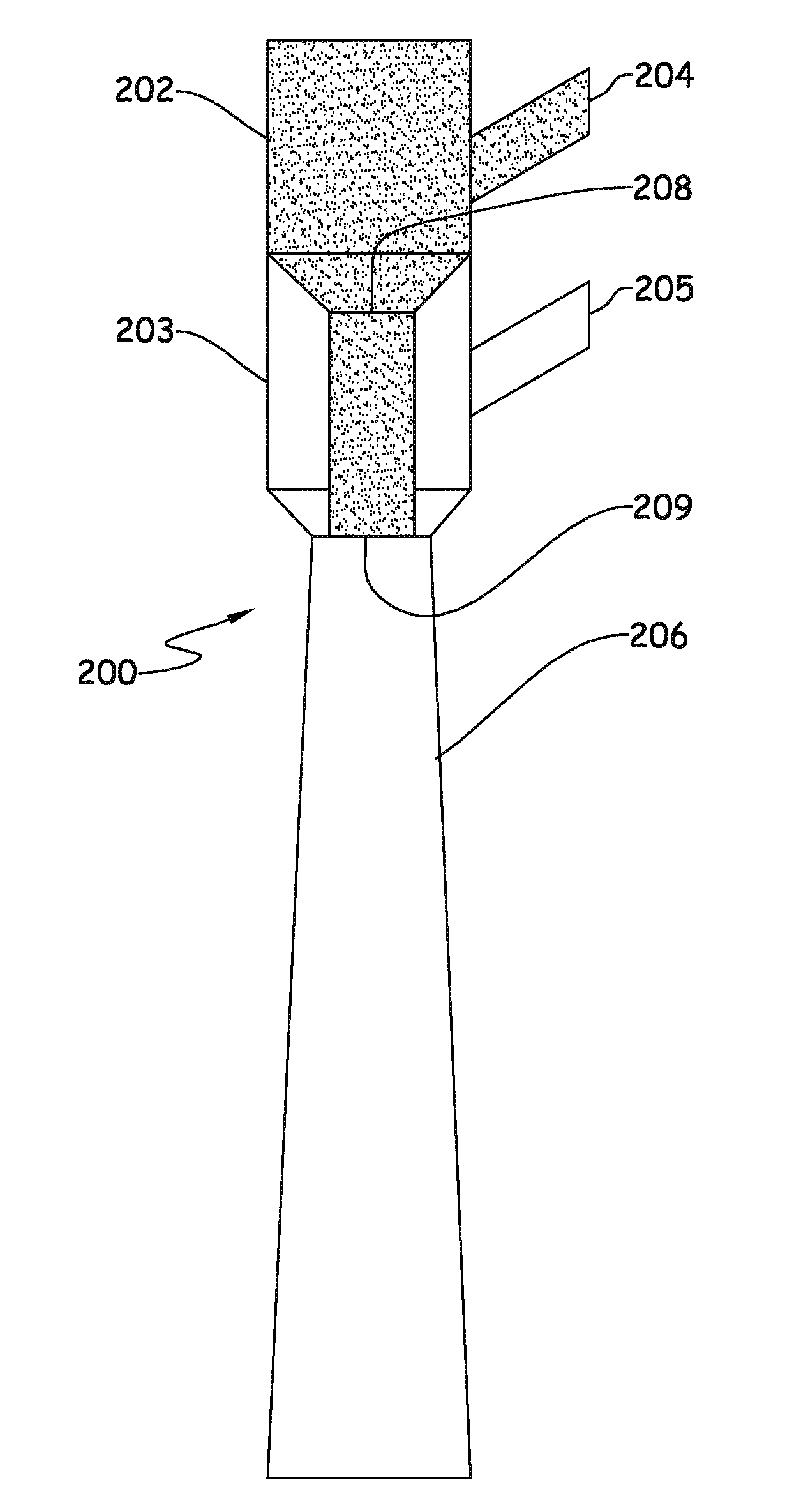
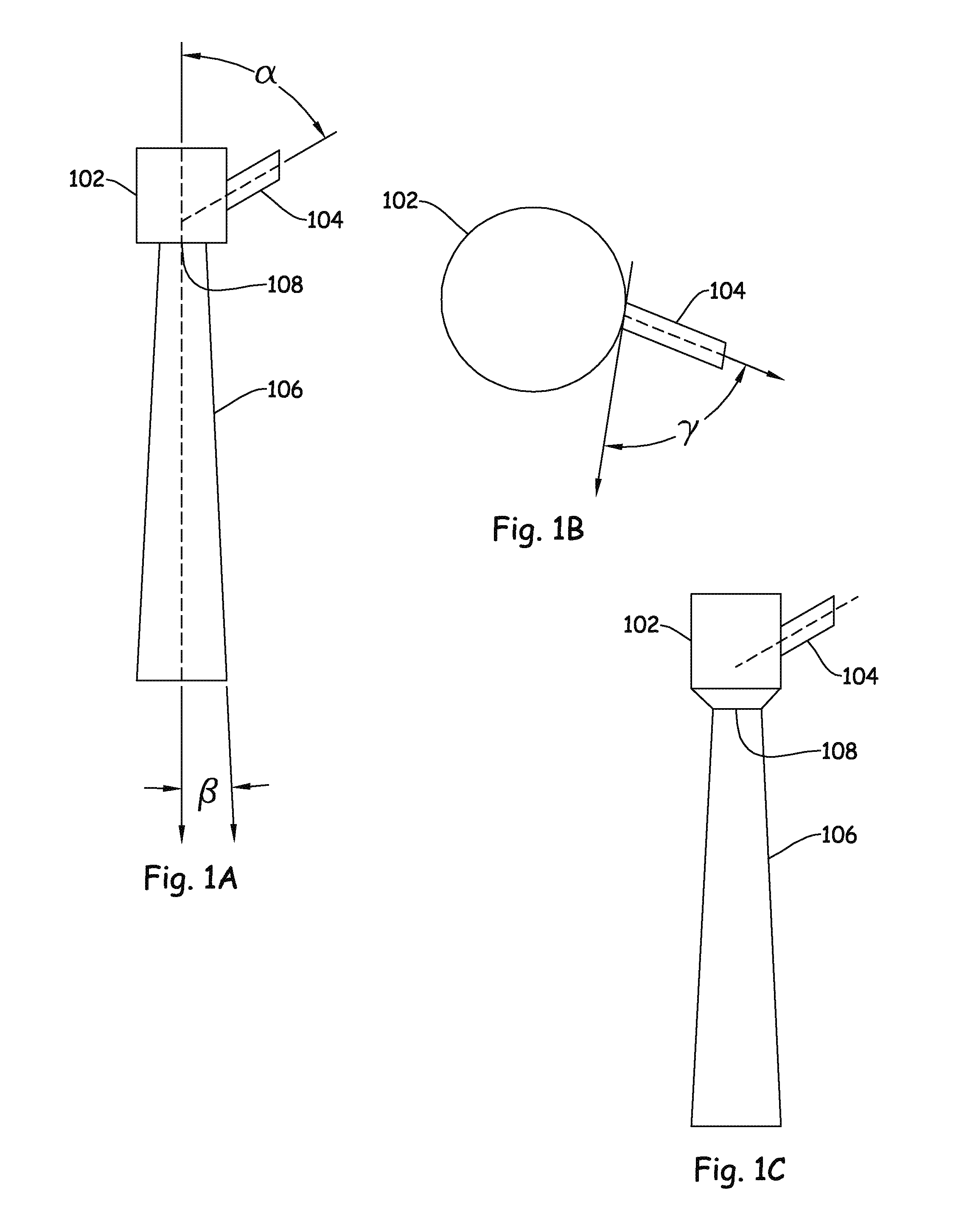
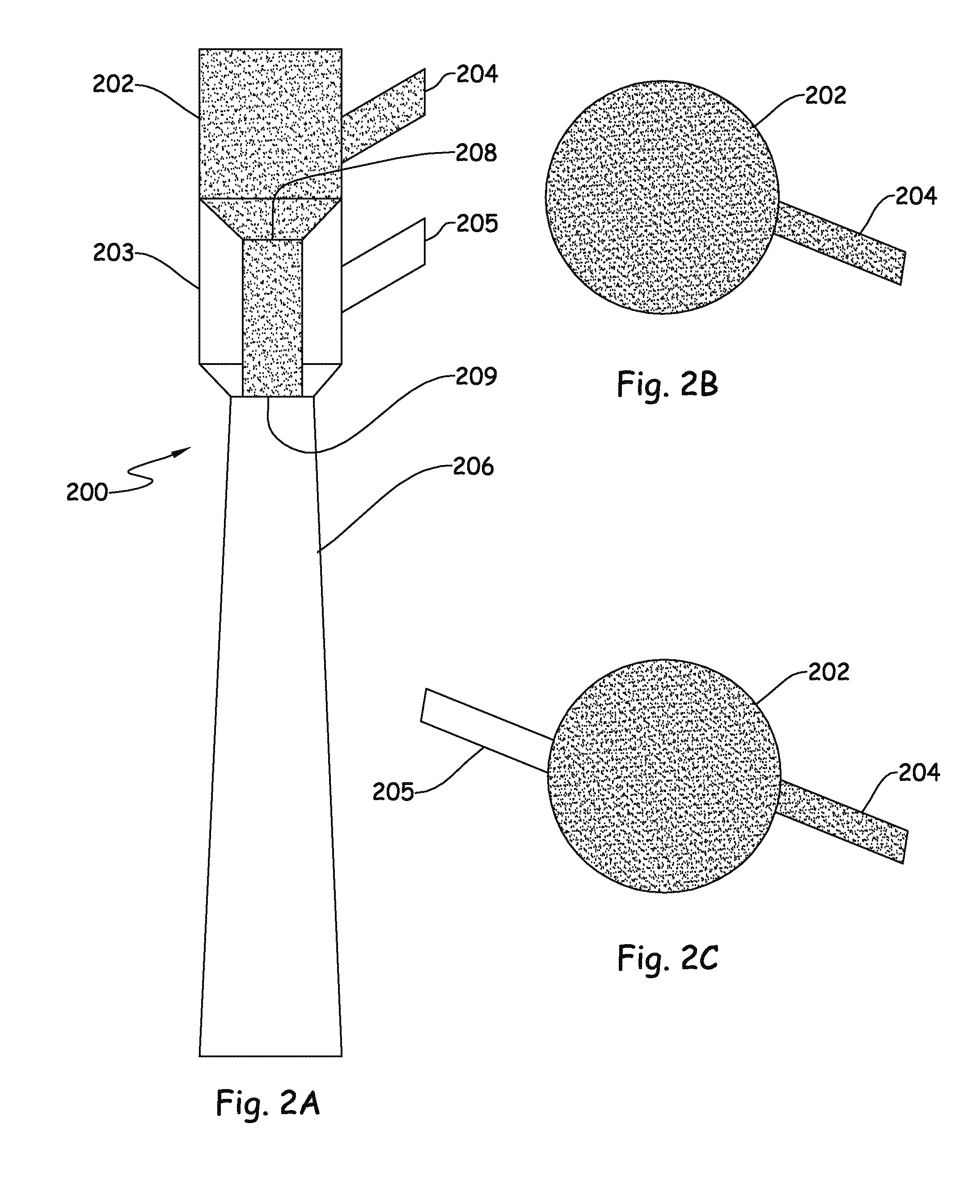
[0070]FIGS. 5A and 5B shows two mixers designed to provide a swirling flow pattern to the reactants provided thereto. In both embodiments, mixer 500 incorporates angle α of 45°, angle β of 7°, and angle γ of 60°. The flow rate of the reactant provided via inlet 504, methyl chloride, is 215.4 kg / hr, while the flow rates of the reactant mixture provided via inlet 505 in the embodiment of mixer 500 shown in FIG. 5A, carbon tetrachloride and perchloroethylene, are 236.5 kg / hr and 10.2 kg / hr, respectively. In the embodiment of mixer 500 shown in FIG. 5B, the reactant mixture provided via inlet 505 in FIG. 5A is provided via an injection port (not shown) in FIG. 5B upstream of the flow pattern development zone. The inner diameter of the outermost chamber outlet (Dco), the outermost tube of the flow pattern development zone, and the mixing zone is 1.5″. The flow development zone length (Lfpd) is 8 inches and the mixing zone (Lm) is 12 inches.

[0071]The results of a computational fluid dynam...


PUM

PropertyMeasurementUnit
chamber-inlet angleaaaaaaaaaa
expander angleaaaaaaaaaa
inner diameteraaaaaaaaaa

Abstract

The present invention relates to a mixer, an apparatus comprising the mixer and a reactor, and processes incorporating the same. The mixer comprises an inlet (104) to a chamber (102), wherein the chamber inlet angle is less than 90°. The mixer further comprises an expander zone (106) that expands outwardly at an expander angle of less than 90°. The mixer may be coupled to a reactor at its outlet, which may closely approximate the size of the reactor inlet due to the expander (106).

Description

FIELD[0001]The present invention relates to an efficient and effective mixer, an apparatus comprising the mixer and a reactor, and processes incorporating the same.BACKGROUND[0002]Hydrofluorocarbon (HFC) products are widely utilized in many applications, including refrigeration, air conditioning, foam expansion, and as propellants for aerosol products including medical aerosol devices. Although HFC's have proven to be more climate friendly than the chlorofluorocarbon and hydrochlorofluorocarbon products that they replaced, it has now been discovered that they exhibit an appreciable global warming potential (GWP).[0003]The search for more acceptable alternatives to current fluorocarbon products has led to the emergence of hydrofluoroolefin (HFO) products. Relative to their predecessors, HFOs are expected to exert less impact on the atmosphere in the form of a lesser or no detrimental impact on the ozone layer and their much lower GWP as compared to HFC's. Advantageously, HFO's also e...

Claims


Application Information

Patent Timeline
Patent Type & Authority Applications(United States)
IPC IPC(8): B01F5/06C07C17/04B01J19/24
CPCB01F5/0653B01J19/24B01J2219/24B01J2219/1943C07C17/04B01J4/002B01F25/102B01F25/4336B01F25/4335
Inventor TIRTOWIDJOJO, MAX M.BAI, HUACALVERLEY, EDWARD M.
Owner BLUE CUBE IP
Why Eureka
Try Eureka