

A renewable energy-based hybrid bi-directionally interactive DC traction power supply system
- Summary
- Abstract
- Description
- Claims
- Application Information
AI Technical Summary
Benefits of technology
Problems solved by technology
Method used
Image

Examples
Embodiment Construction
[0032]Detailed description of a renewable energy-based hybrid bi-directionally interactive DC traction power supply system of the invention will be made with reference to embodiments and drawings.
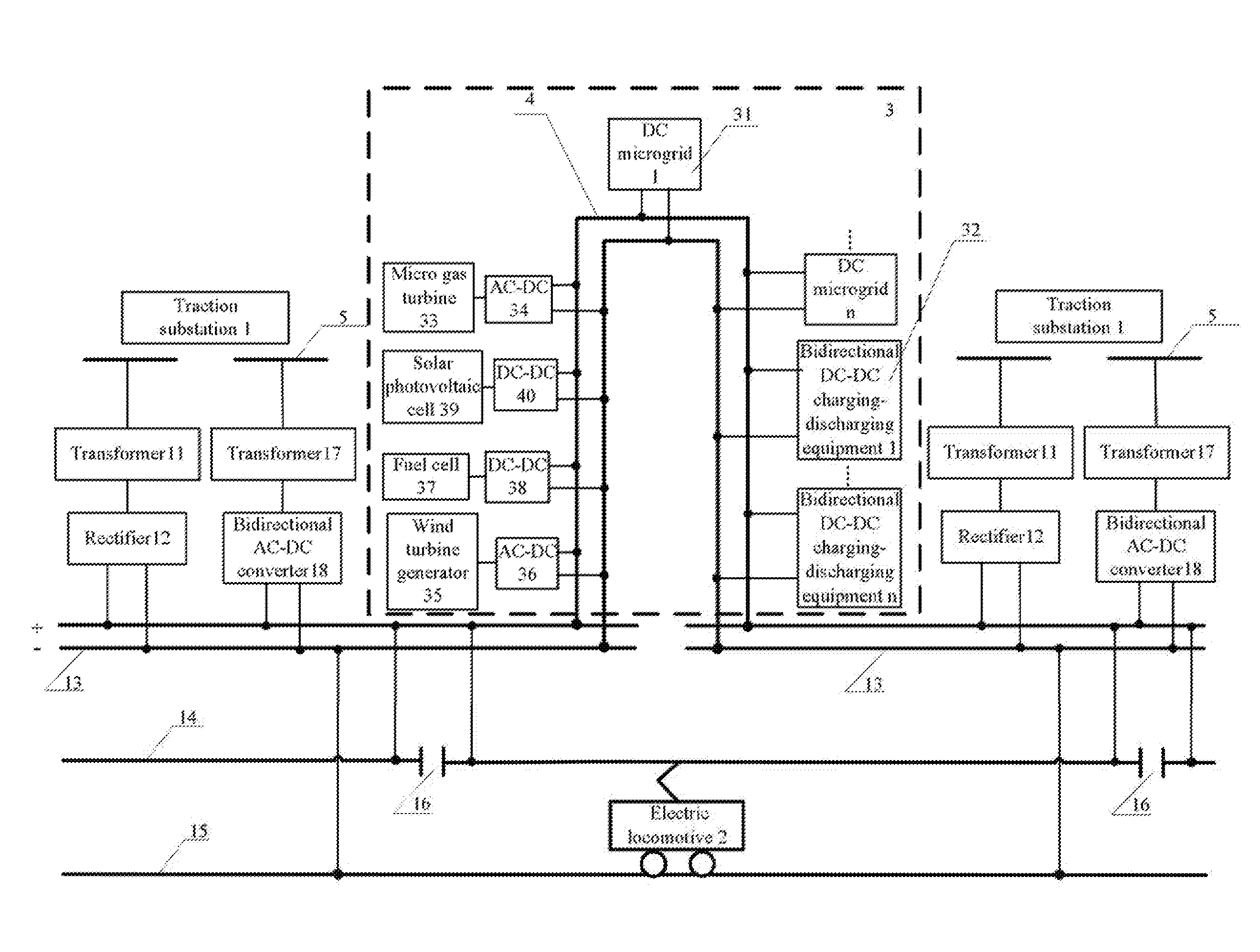
[0033]According to the current invention, there is provided a renewable energy-based hybrid bi-directionally interactive DC traction power supply system. It is a DC microgrid produced which incorporates distributed generation, charging and discharging system of electric vehicle mainly employing battery-swapping, and DC traction power supply system. The present invention proposes a bidirectional interactive DC traction power supply system.
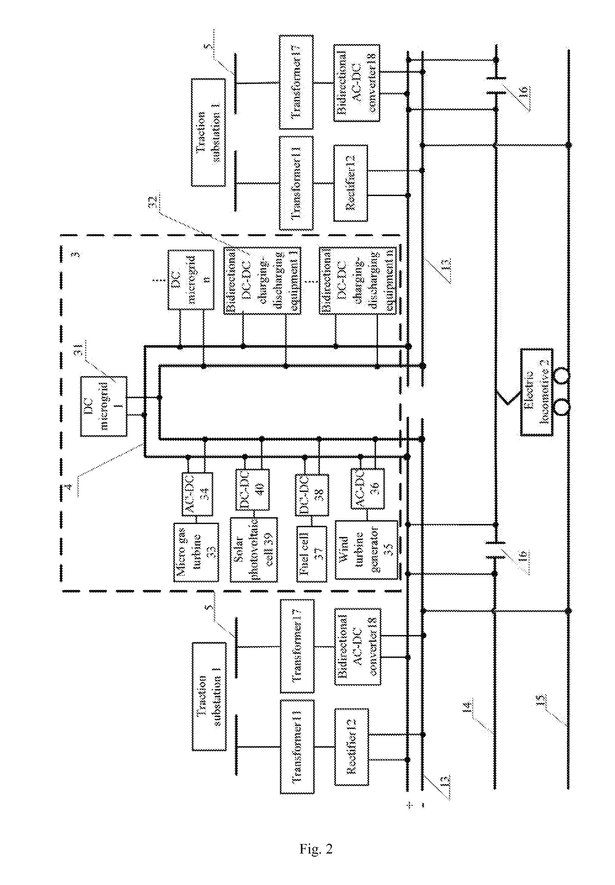
[0034]The present invention provides a renewable energy-based hybrid bi-directionally interactive DC traction power supply system powered bilaterally, i.e., a bidirectional interactive DC traction power supply system based on paralleled and combined rectifier and bidirectional AC-DC converter. As denoted in FIG. 2, a renewable energy-based hybrid bi-directi...
PUM
 Abstract
Description
Claims
Application Information