

Photobioreactor system for air purification by using microalgae
a photobioreactor and microalgae technology, applied in the field of air purification, can solve problems affecting the performance of the photobioreactor, and achieve the effect of high-efficiency removal of carbon dioxid
- Summary
- Abstract
- Description
- Claims
- Application Information
AI Technical Summary
Benefits of technology
Problems solved by technology
Method used
Image

Examples
example 1
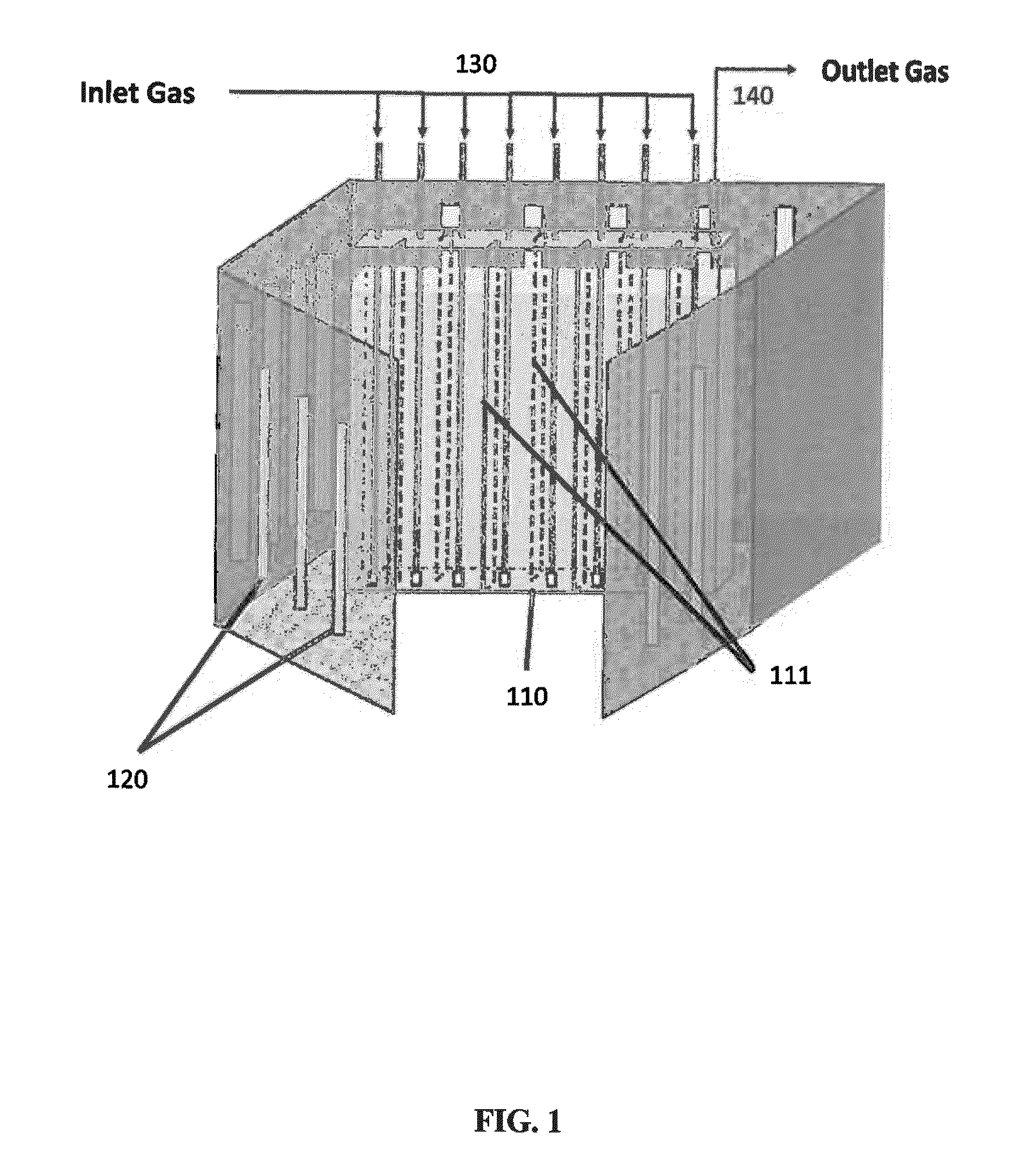
[0043]Purification of CO2 polluted air using the present invention as shown in FIG. 1 is carried out. The reactor is panel shaped reactor with a single partition. The volume of the reactor is 4 L. The reactor is operated indoors. An initial concentration of Chlorella sp. in modified Bold's Basal medium is 1,200,000 cells of microalgae / mL medium. The temperature of the microalgae culture medium is 30° C. A LED setup radiates light continuously at 400 μmol / m2s−1. The operation cycle is two weeks. The CO2 concentration of the inlet gas is 490 ppm and its flow rate is 1000 mL / min. After 24 hours, the concentration of the CO2 in the outlet gas is measured to be 146 ppm, with a consumption of 70% CO2. The reactor is able maintain over 70% CO2 consumption for the two week operation cycle. The graph showing the CO2 consumption performance over the operation period of two weeks is shown in FIG. 4
example 2
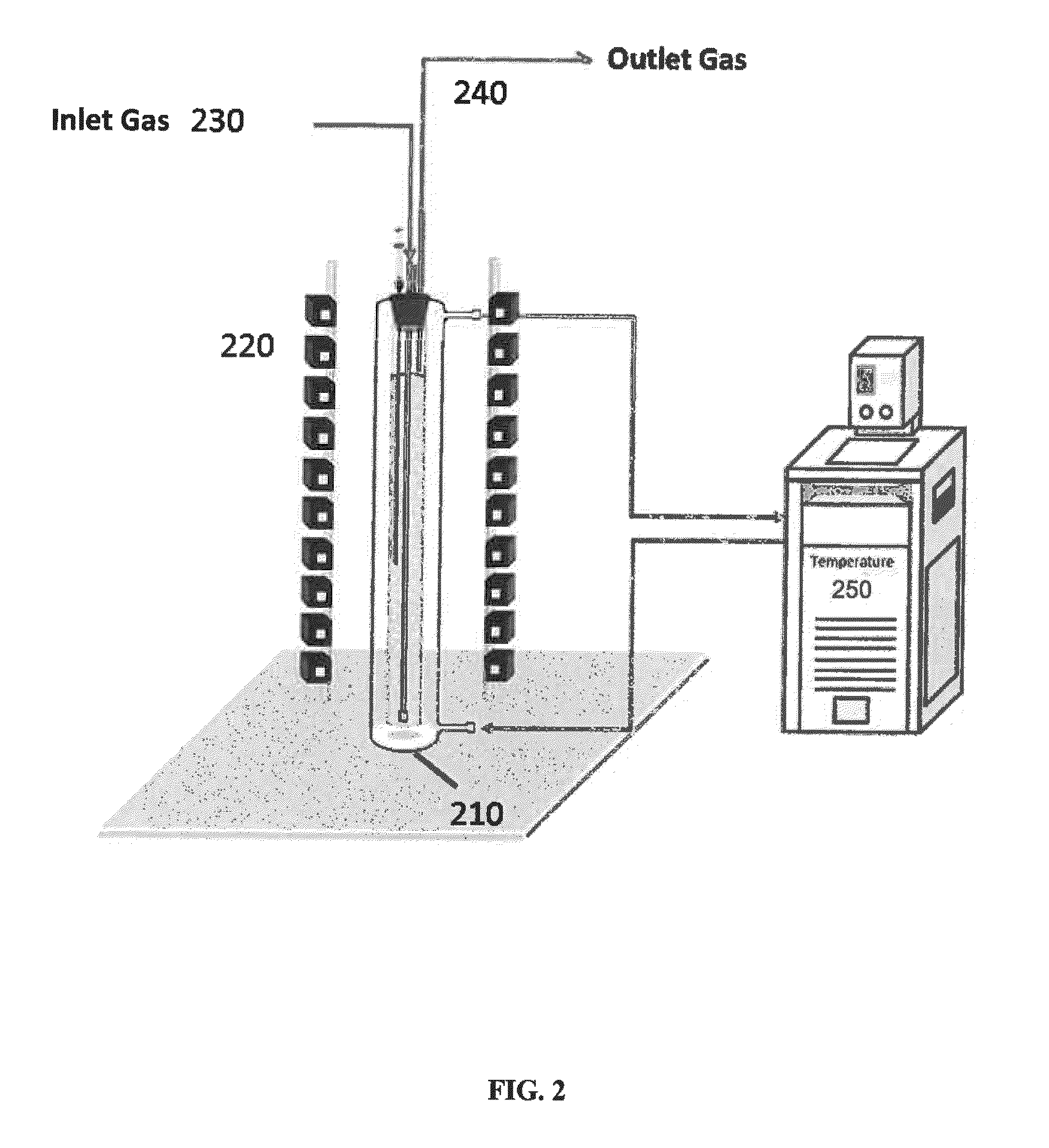
[0044]Purification of CO2 polluted air using the present invention as shown in FIG. 2 is carried out. The reactor is a tubular reactor with a volume of 1000 ml, the diameter to height ratio is 1:10. The reactor is operated indoors. An initial concentration of Chlorella sp. in modified Bold's Basal medium is 1,200,000 cells of microalgae / mL medium. The temperature of the microalgae culture medium is 30° C. A LED setup radiates light continuously at 400 μmol / m2s−1. The CO2 concentration of the inlet gas is 450 ppm and its flow rate is 1000 mL / min. After 24 hours, the concentration of the CO2 in the outlet gas is measured to be 90 ppm, with a CO2 consumption of over 80% The reactor is able maintain over 80% CO2 consumption for 250 hours of operation. The graph showing the CO2 consumption performance over the operation period of two weeks is shown in FIG. 5.
example 3
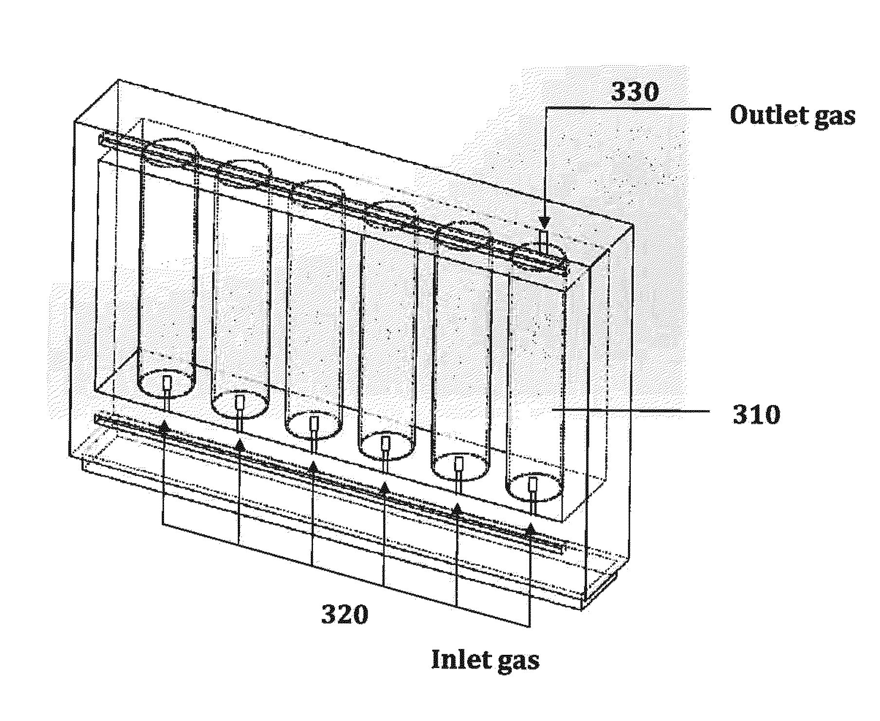
[0045]Purification of CO2 polluted air using the present invention as shown in FIG. 3 is carried out. The reactor is a tubular reactor with a volume of 100 L, the diameter to height ratio is 1:5. Six reactors are operating in parallel. The reactor is operated in an outdoor site. An initial concentration of Chlorella sp. in modified Bold's Basal medium is 1,200,000 cells of microalgae / mL medium. Sunlight provides natural illumination to the microalgae culture medium. The CO2 concentration of the inlet gas is 400 ppm and its flow rate is 10 L / min. After 72 hours, the concentration of the CO2 in the outlet gas is measured to be 45 ppm, with a CO2 consumption of over 80% The reactor is able maintain over 80% CO2 consumption for 18 days of operation and 40%. CO2 consumption for 30 days of operation. The graph showing the CO2 consumption performance over the operation period of one month is shown in FIG. 6
[0046]The foregoing description of the present invention has been provided for the p...
PUM
| Property | Measurement | Unit |
|---|---|---|
| flow rate | aaaaa | aaaaa |
| temperature | aaaaa | aaaaa |
| temperature | aaaaa | aaaaa |
Abstract
Description
Claims
Application Information