
Apparatus and method for controlling battery state of charge in hybrid electric vehicle

a hybrid electric vehicle and state of charge technology, applied in the direction of process and machine control, vehicle sub-unit features, external condition input parameters, etc., can solve the problems of increasing the transient control section, reducing energy efficiency and operability, and consuming a lot of energy. , to achieve the effect of maximizing the energy recovery of the motor, improving fuel efficiency and operability, and efficient use of energy

Active Publication Date: 2016-06-16
HYUNDAI MOTOR CO LTD +1
View PDF10 Cites 54 Cited by
  • Summary
  • Abstract
  • Description
  • Claims
  • Application Information

AI Technical Summary

Benefits of technology

This patent describes a method for controlling the battery charge in a hybrid electric vehicle. The method aims to use energy efficiently, maximize energy recovery, and improve fuel efficiency and operability without improving the performance of the electrical equipment or the main battery. The method also takes into account the vehicle's speed, road type, and traffic situation to predict and minimize transient states, such as sudden changes in speed or road slope. The method also restricts excessive charging and discharging of the main battery to prevent driving disablement. Overall, the method ensures that the vehicle runs smoothly and safely while saving energy and improving efficiency.

Problems solved by technology

Generally, internal combustion engine vehicles that use fossil fuels such as gasoline and diesel have a variety of limitations such as environmental contamination caused by the engine exhaust, global warming caused by carbon dioxide, and respiratory illnesses caused by creation of ozone.
In particular, when a vehicle enters a uphill road or a low-speed section, or when a vehicle enters a downtown or a congested section and when the battery state of charge (hereinafter, referred to as ‘SOC’) (%) is low, an available motor torque is limited upon EV driving reduction and acceleration / deceleration, generating an increase of a transient control section and thus reducing the energy efficiency and operability (e.g., charge amount at idle and inefficiency operating point increases).
Further, when a vehicle enters a downhill road or a middle / high-speed section or when a vehicle enters a highway or an expressway, when the battery SOC (%) is high, an available batter space for charge is deficient upon regenerative braking and coast regeneration, making it difficult to recover extra regenerative energy and thus wasting the regenerative energy.
Particularly, when there is frequent regenerative braking for maintaining a vehicle at a constant speed, or when a vehicle travels on a long-distance deceleration or downhill road such as the outlet of an expressway, regenerative energy may not be recovered and may be wasted.
In the related art, since the slope of a driving road is predicted from a signal of an accelerator (e.g., acceleration pedal) position sensor (APS), an output, a vehicle speed, or a signal of a G sensor (e.g., acceleration sensor) to determine a SOC control strategy or since the SOC control strategy is determined based on an APS signal, a brake pedal position sensor (BPS), or vehicle speed, an increase of a transient control section may occur and thus reductions of fuel efficiency and operability may be incurred due to misdetermination or determination delay according to variations (e.g., change of road load, change of acceleration or deceleration situation) of vehicle driving conditions during control section determination.

Method used


Image

  • Apparatus and method for controlling battery state of charge in hybrid electric vehicle
  • Apparatus and method for controlling battery state of charge in hybrid electric vehicle
  • Apparatus and method for controlling battery state of charge in hybrid electric vehicle

Examples


Embodiment Construction

[0043]Although exemplary embodiment is described as using a plurality of units to perform the exemplary process, it is understood that the exemplary processes may also be performed by one or plurality of modules. Additionally, it is understood that the term controller / control unit refers to a hardware device that includes a memory and a processor. The memory is configured to store the modules and the processor is specifically configured to execute said modules to perform one or more processes which are described further below.

[0044]Furthermore, control logic of the present invention may be embodied as non-transitory computer readable media on a computer readable medium containing executable program instructions executed by a processor, controller / control unit or the like. Examples of the computer readable mediums include, but are not limited to, ROM, RAM, compact disc (CD)-ROMs, magnetic tapes, floppy disks, flash drives, smart cards and optical data storage devices. The computer re...


PUM


Abstract

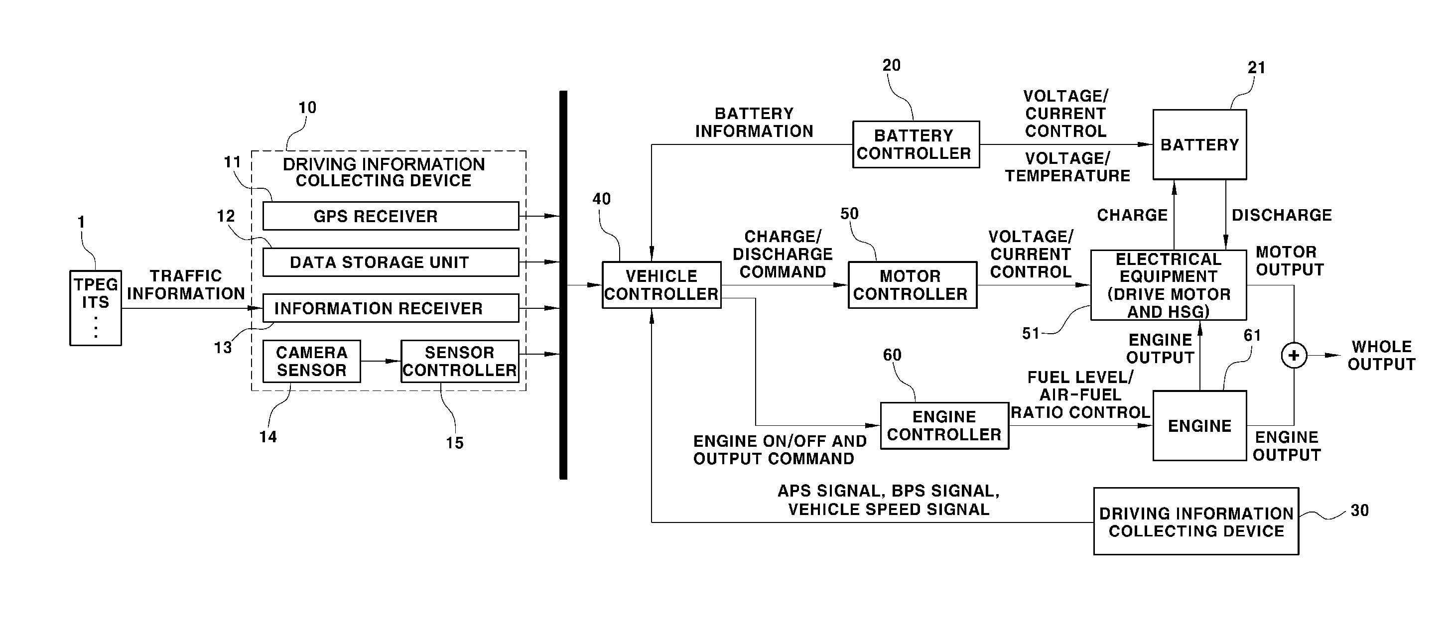
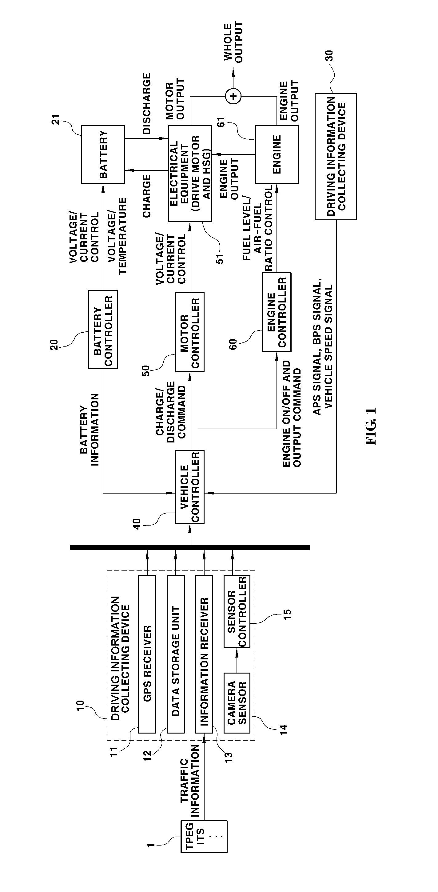
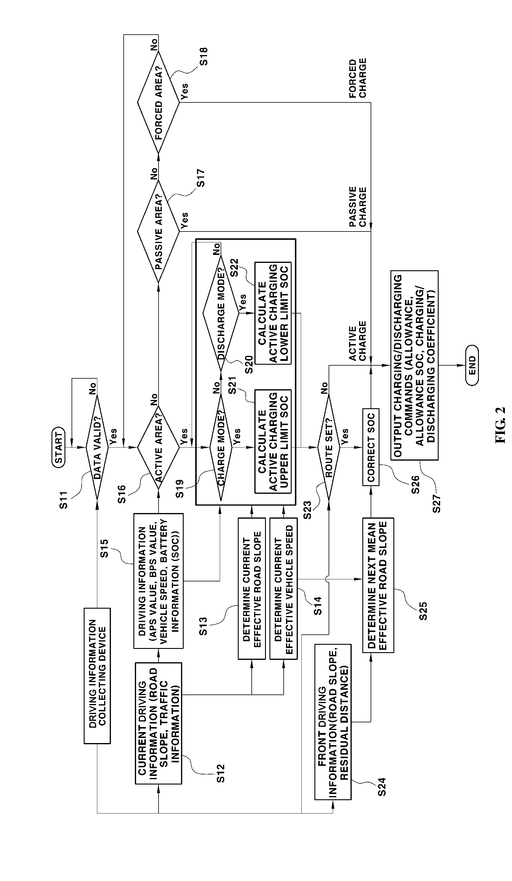
A method and apparatus for controlling battery state of charge (SOC) in a hybrid electric vehicle are provided to enable the efficient use of energy, the maximization of energy recovery, and the improvement of fuel efficiency and operability without the improvement of capacity and performance of electrical equipment or a main battery in a hybrid electric vehicle. The apparatus includes a collecting device that collects information regarding the slope or the road type and information regarding the vehicle speed. A controller determines charge and discharge modes based on the driving information and determines a charging upper and lower limit SOC based on the road slope or road type information a road section on which the vehicle is traveling and the vehicle speed information in the road section. A charge or discharge command is output based on the charging upper limit SOC and the charging lower limit SOC.

Description

CROSS-REFERENCE TO RELATED APPLICATION[0001]This application claims under 35 U.S.C. §119(a) the benefit of Korean Patent Application No. 10-2014-0178658 filed Dec. 11, 2014, the entire contents of which are incorporated herein by reference.BACKGROUND[0002](a) Technical Field[0003]The present invention relates to a method for controlling battery State of Charge (SOC) in a hybrid electric vehicle. More particularly, the present invention relates to a method for controlling battery state of charge in a hybrid electric vehicle, which enables the efficient use of energy, the maximization of energy recovery by a motor, and the improvement of fuel efficiency and operability without the improvement of capacity and performance of electrical equipment (drive motor, Hybrid Starter and Generator (HSG), etc.) or a main battery in a hybrid electric vehicle.[0004](b) Background Art[0005]Generally, internal combustion engine vehicles that use fossil fuels such as gasoline and diesel have a variety ...

Claims


Application Information

Patent Timeline
Patent Type & Authority Applications(United States)
IPC IPC(8): B60W20/13G06K9/32G01S19/42G06K9/00B60K6/20G08G1/0967
CPCB60W20/13B60K6/20G08G1/096708G01S19/42G06K9/00818B60Y2400/61Y10S903/903B60Y2200/10B60Y2300/91B60Y2400/303G06K9/3258B60W10/26B60W20/00B60W2520/10B60W2552/05B60W2552/15B60L2240/60B60L2240/642B60L2240/68Y02T90/16Y02T10/92G08G1/091G08G1/09623G08G1/09626G08G1/096775B60W2710/244B60W20/12B60L58/12B60W2552/20B60W2554/00B60W2555/60B60W2556/50Y02T10/70Y02T10/72G06V20/582B60W40/02B60W40/04Y02T10/62B60W2554/406
Inventor YOON, DONG PIL
Owner HYUNDAI MOTOR CO LTD
Learn More