Method for controlling an engine braking device and engine braking device

a technology of engine braking and braking device, which is applied in the direction of exhaust gas recirculation, output power, mechanical apparatus, etc., can solve the problems of insufficient ensuring, and achieve the effects of reducing the flow rate of exhaust gas, increasing the inlet-side boost pressure, and increasing the mass flow

Active Publication Date: 2016-06-16
MAN TRUCK & BUS OESTERR
View PDF6 Cites 28 Cited by
  • Summary
  • Abstract
  • Description
  • Claims
  • Application Information

AI Technical Summary

Benefits of technology

[0015]Also in the case of the engine braking device according to the invention, the brake flap is preferably arranged upstream of an exhaust turbine of the exhaust turbocharger, most preferably directly upstream of and adjacent to the exhaust turbine, and thus forms a flow guiding flap which (positively) influences gas admission to the exhaust turbine. It is thereby possible to greatly increase the inlet-side boost pressure in the engine braking mode, virtually without additional outlay on construction, and thus to increase the mass flow required in the combustion engine for the achievable braking power. The brake flap thus performs several functions simultaneously: it ensures, preferably under closed-loop control, a sufficient exhaust gas backpressure and additionally ensures advantageous inflow to the turbine with a reduced exhaust gas flow rate and lower exhaust gas enthalpy, similarly to the operation of a control flap on exhaust turbines with variable turbine geometry. More specifically, in contrast to a brake flap arranged downstream of the exhaust turbine, the brake flap arranged upstream of the exhaust turbine (preferably directly upstream of and adjacent to the exhaust turbine) here brings about a higher pressure gradient across the exhaust turbine, as a result of which, due to the higher mass flow and volume flow which is then possible through the exhaust turbine, the boost pressure and the exhaust gas backpressure can be significantly increased and thus also the engine braking power can be significantly increased in a functionally reliable manner without thermal overloading of the combustion engine. By virtue of the pressure gradient across the brake flap arranged upstream, lower loading of the exhaust turbine is achieved here for the same exhaust gas backpressure, and hence this leads to the desired increase in braking power with an increase in the exhaust gas backpressure, without higher loading of the exhaust turbine.
[0016]In one embodiment, the brake flap is arranged upstream of and outside, preferably directly upstream of and outside, a turbine housing of an exhaust turbine of the exhaust turbo-charger (and therefore upstream of an inflow duct of the turbine housing). Through the arrangement of the at least one brake flap upstream of and hence outside a turbine housing or an inflow duct of the exhaust turbine, the flap does not form a component of the exhaust turbine, this resulting in positioning of the brake flap for easy assembly with increased degrees of freedom in terms of design. In particular, it is then possible here to avoid structural modifications to the exhaust turbine, and there is no need to stock a large number of different turbines for different model series. According to a specific first embodiment that is particularly preferred for this purpose, the exhaust turbine, in particular a turbine housing of the exhaust turbine, can then be coupled fluidically here to an exhaust manifold, to which the exhaust gas is admitted via at least one, preferably a plurality of, cylinders of the combustion engine, wherein a separate module having the brake flap is installed between the exhaust turbine and the exhaust manifold, in particular between a turbine housing of the exhaust turbine and the exhaust manifold and hence directly upstream of and outside a turbine housing of the exhaust turbine, the module being firmly connected both to the turbine housing and to the exhaust manifold. In a manner which is particularly compact and advantageous in terms of construction, provision is made, according to a second specific embodiment, for the exhaust turbine or an exhaust turbine housing of the exhaust turbocharger to be mounted directly on an exhaust manifold, to which the exhaust gas is admitted via at least one, preferably a plurality of, cylinders of the combustion engine, wherein the brake flap is arranged in the region of the exhaust manifold and hence directly upstream of and outside a turbine housing of the exhaust turbine.

Problems solved by technology

It has been recognized that the exhaust gas backpressure as an available control variable for selectively activating the decompression brake on the basis of the variation in the pressure conditions due to the boost pressure of a pressure-charged combustion engine is not sufficient to ensure selective initiation or control of the decompression brake or of the respectively demanded braking power in the engine braking mode.

Method used


Image

  • Method for controlling an engine braking device and engine braking device
  • Method for controlling an engine braking device and engine braking device
  • Method for controlling an engine braking device and engine braking device

Examples


Embodiment Construction

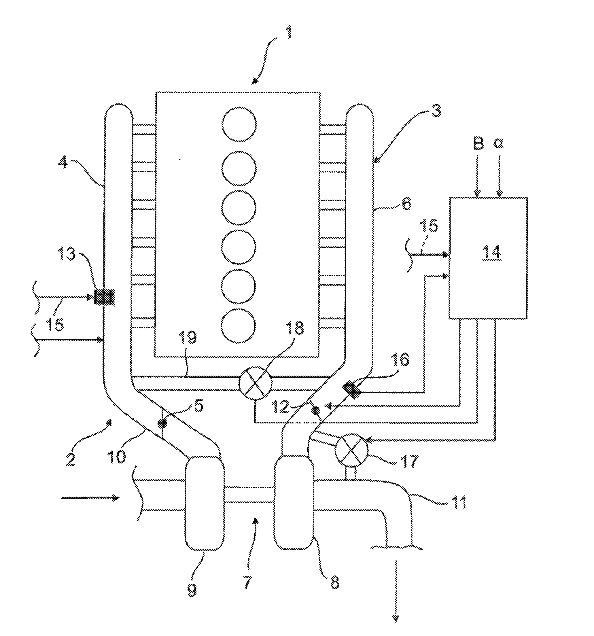
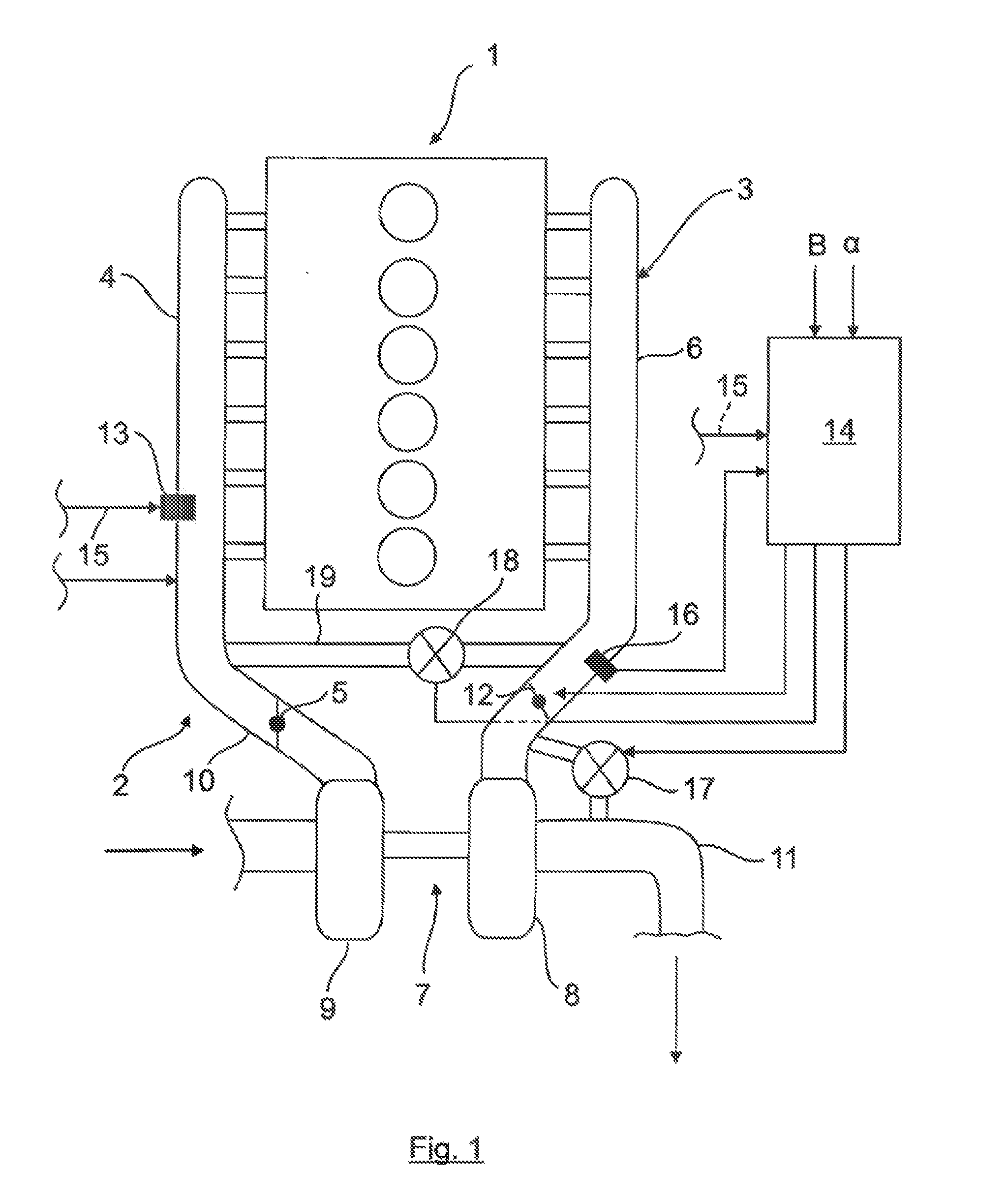
[0027]A combustion engine 1 (e.g., a six-cylinder diesel combustion engine), in particular for a commercial vehicle, having an intake system 2 and an exhaust system 3 (of conventional construction where not described) is shown in a purely schematic way in FIG. 1. A throttle valve 5 can optionally be provided in the intake manifold 4 of the intake system 2.

[0028]The exhaust system 3 has an exhaust manifold 6, which is connected to the combustion chambers of the combustion engine 1 and is connected directly or indirectly to the exhaust turbine 8 of an exhaust turbocharger 7. The exhaust turbine 8 drives a compressor 9 in a known manner, the compressor being connected, in turn, to the intake manifold 4 by a line 10 and delivering combustion air at a defined boost pressure PL to the combustion chambers of the combustion engine 1. The exhaust gas flowing out via the exhaust manifold 6 and the exhaust turbine 8 is carried away further by an exhaust line 11. The other lines of the intake s...


PUM


Abstract

The invention relates to a method for controlling an engine braking device for a combustion engine in motor vehicles, wherein the engine braking device has an intake system, an exhaust system, gas exchange valves associated with the combustion engine, exhaust turbo-charging by at least one exhaust turbocharger integrated into the exhaust system and the intake system, and an engine braking unit, wherein the engine braking unit has a decompression brake, which influences at least one outlet valve of the gas exchange valves and is dependent on the exhaust gas backpressure, and a brake flap, which is arranged in the exhaust system. To achieve a precisely controllable engine braking power in the engine braking mode, the demanded braking torque is controlled in accordance with the boost pressure of the exhaust turbocharger and with the exhaust gas backpressure upstream of the brake flap, which is arranged directly upstream of an exhaust turbine of the exhaust turbocharger. A suitable engine braking device is furthermore proposed.

Description

CROSS-REFERENCE TO RELATED APPLICATIONS[0001]The present application claims priority of A 910 / 2014 filed Dec. 15, 2014, which is incorporated herein by reference.BACKGROUND OF THE INVENTION[0002]The present invention relates to a method for controlling an engine braking device for a combustion engine in motor vehicles, in particular in commercial vehicles, to an engine braking device, and to a vehicle having the engine braking device.[0003]In air-compressing (diesel) combustion engines in commercial vehicles, there is a known practice of producing an exhaust gas backpressure in the exhaust system using a brake flap in the overrun mode, the backpressure bringing about effective engine braking since the pistons of the combustion engine operate against this exhaust gas pressure during the exhaust stroke (outlet valves open).[0004]In order significantly to increase the effect of such an engine braking device, there is a practice known from U.S. Pat. No. 8225769 B2 for example, of additi...

Claims


Application Information

Patent Timeline
Patent Type & Authority Applications(United States)
IPC IPC(8): F02D13/04F01L13/06
CPCF01L13/06F02D13/04F02B37/12F02D9/06F02B37/24F02B37/02F02B37/18F02B37/22F02M26/05Y02T10/12
Inventor RAMMER, FRANZKLINGER, HEIDRUNKREUZRIEGLER, ANDRE
Owner MAN TRUCK & BUS OESTERR
Why Eureka
Try Eureka