Biological fluid flow control apparatus and method

a flow control and biological fluid technology, applied in the direction of fluid pressure control, positive displacement liquid engine, instruments, etc., can solve the problems of increasing procedure time and greater burden on the operator, occlusion alarm, and inability to increase to exceed the maximum flow rate, so as to reduce the fluid flow rate

Active Publication Date: 2016-06-23
FENWAL
View PDF8 Cites 4 Cited by
  • Summary
  • Abstract
  • Description
  • Claims
  • Application Information

AI Technical Summary

Benefits of technology

[0010]For illustrative summary purposes, in accordance with one aspect of the present subject matter, a method is provided for controlling flow through a biological fluid processing device (such as a blood apheresis device) fluid flow path. The fluid may be, for example, blood components being returned to a donor, replacement fluid, a combination of both and/or another infusion fluid. In this description, references to infusion and return may be used interchangeably and include but are not limited to apheresis systems where the subject is typically a living donor. The method includes: (1) flowing fluid through the fluid flow path at a flow rate; monitoring the pressure of fluid flowing in the fluid flow path; and increasing the flow rate of fluid in the fluid flow path by a first selected amount if the monitored pressure is below a first pressure level for at least a first amount of time, with the first pressure level being below a maximum allowed pressure level; and (2) decreasing the fluid flow rate in the fluid flow path by a second selected amount if the monitored pressure is above a second pressure level for a second amount of time, with the second pressure level being below the maximum allowed pressure level and above the first pressure level.
[0011]In accordance with another aspect of the present subject matter, a durable biological fluid processing device may be provided for processing biological fluid in a

Problems solved by technology

Another complicating factor is fluid flow path occlusions, which may lead to occlusion alarms.
In prior systems, such occlusions are commonly detected by the processing system from increased fluid pressure within the infusion fluid flow path, and typically resulted in an alarm condition being generated to alert the system operator of the occlusion.
Of course, the requirement for operator interven

Method used


Image

  • Biological fluid flow control apparatus and method
  • Biological fluid flow control apparatus and method
  • Biological fluid flow control apparatus and method

Examples


Embodiment Construction

[0022]The embodiments disclosed herein are for the purpose of providing an exemplary description of the present subject matter. They are only exemplary, however, and the present subject matter may be embodied in various forms. Therefore, specific details disclosed herein are not to be interpreted as limiting the subject matter as defined in the accompanying claims.

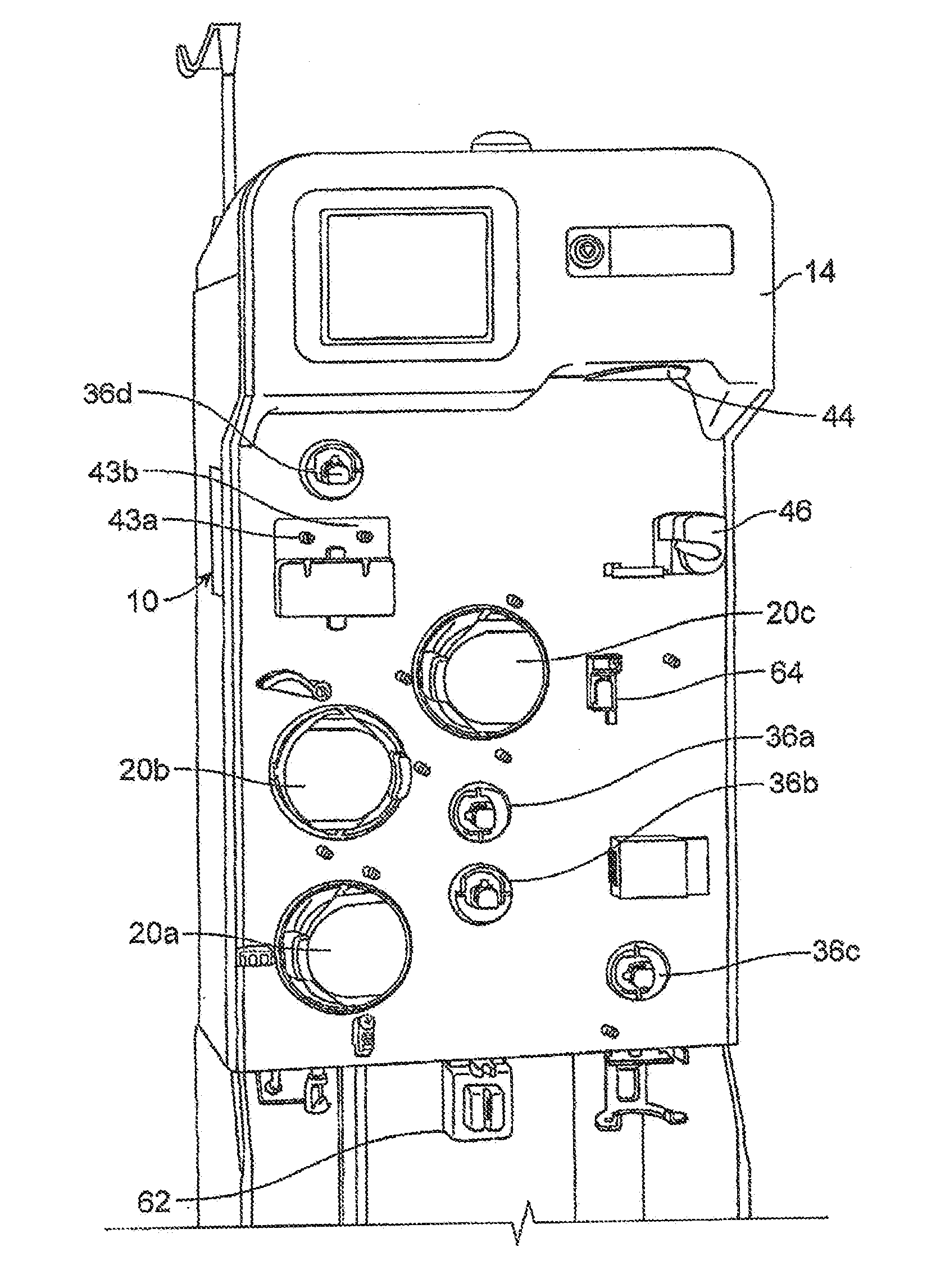
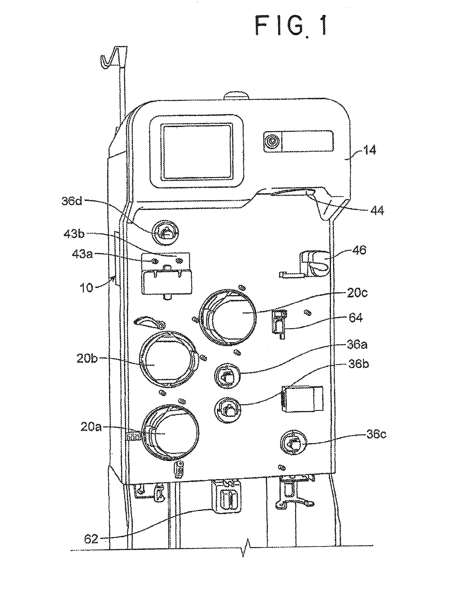
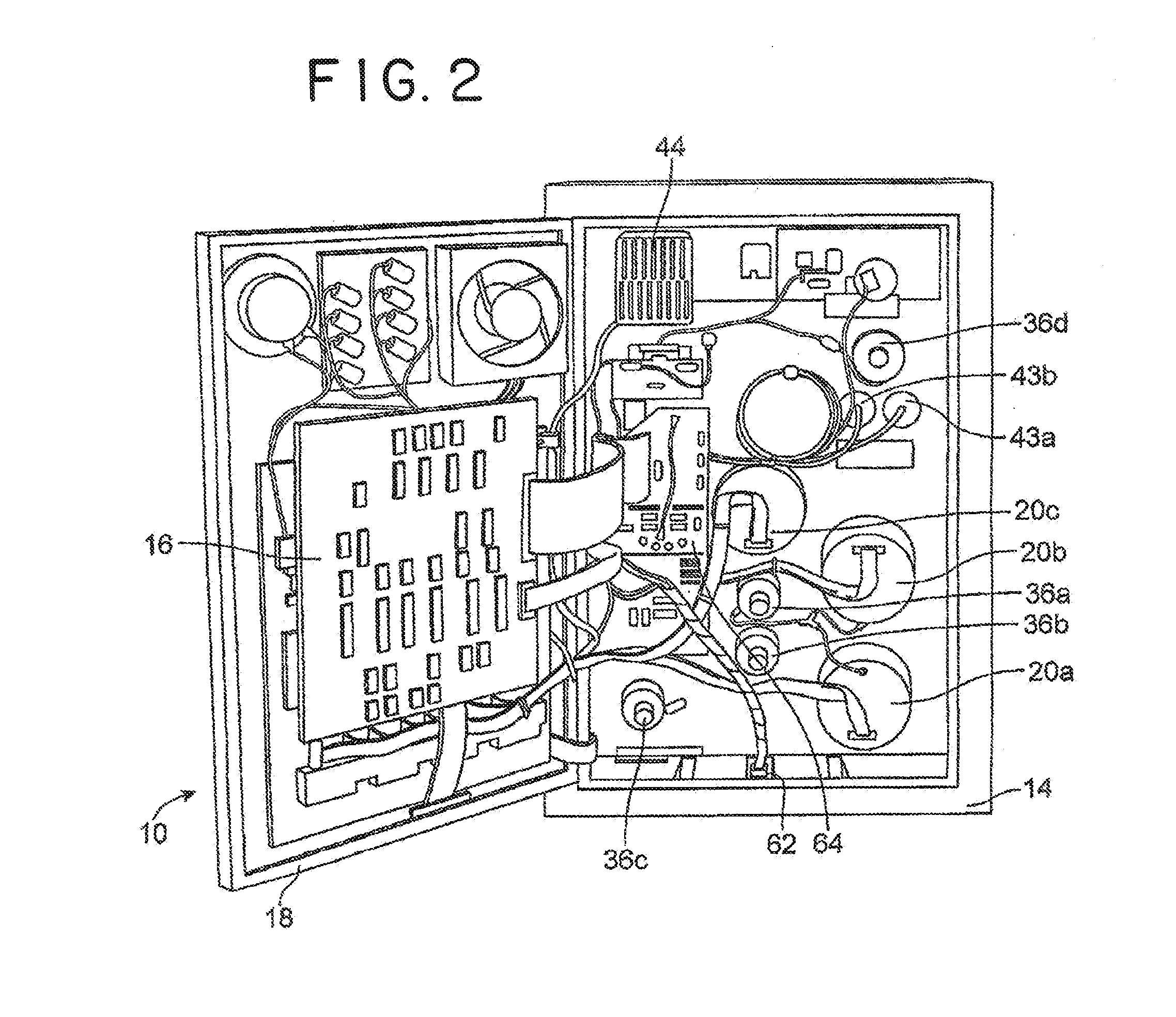
[0023]According to an aspect of the present disclosure, a durable or reusable fluid separation system is used in combination with a separate fluid flow circuit (which may be disposable) to separate a fluid into two or more constituent parts. FIGS. 1 and 2 illustrate an exemplary fluid separation system 10, while FIG. 3 illustrates an exemplary fluid flow circuit 12 mounted onto the fluid separation system 10, but it should be understood that the illustrated fluid separation system 10 and fluid flow circuit 12 are merely exemplary of such systems and circuits and that differently configured fluid separation systems and flui...


PUM


Abstract

Apparatus, system and method are provided for controlling flow through a biological fluid processing device. Pressure of fluid flow through a flow path is monitored and flow rate in the flow path is increased or decreased based on sensed pressure levels for selected periods of time. This has particular application in controlling flow in an infusion or return flow path of an apheresis device that separates whole blood into one or more blood components.

Description

BACKGROUND[0001]1. Field of the Disclosure[0002]The subject matter of this application relates generally to biological fluid processing systems and methods such as biological fluid separation systems and methods. More particularly, the subject matter relates to methods, devices and systems for controlling fluid flow and, more particularly, for controlling flow rates and pressures in a fluid flow path such as a return or infusion flow path that may be connected to a human subject.[0003]2. Description of Related Art[0004]Various blood processing systems now make it possible to collect and / or process particular blood constituents, instead of whole blood, from a blood source such as, but not limited to, a container of previously collected blood or other living or non-living source. Typically, in such systems, whole blood is drawn from a blood source, a particular blood component or constituent is separated, removed, and collected, and the remaining blood constituents are returned to the...

Claims


Application Information

Patent Timeline
IPC IPC(8): A61M1/34G05D7/06G05D16/20G01F7/00
CPCA61M1/3496G01F7/005A61M2205/3337G05D16/2066G05D7/0676A61M1/02A61M1/024A61M1/0259A61M1/38A61M2205/3334A61M2205/3331A61M1/3639A61M5/16831A61M5/16854A61M2005/16863A61M2005/16868A61M2205/3341A61M1/3607A61M5/14212A61M2205/18A61M2205/50A61M1/341A61M1/3621
Inventor PATEL, AMIT J.PLANAS, SAMANTHA M.HIGGINSON, KATHLEEN M.THILL, MELISSA A.MOORE, COURTNEY
Owner FENWAL
Why Eureka
Try Eureka