Engine and method for operating said engine

a technology for engines and rotors, applied in the field of working engines and gas turbines, can solve the problems of more difficult to guide the cooling air to the rotor parts, and achieve the effect of improving the efficiency of cooling air

Inactive Publication Date: 2016-06-23
ANSALDO ENERGIA SWITZERLAND AG
View PDF16 Cites 8 Cited by
  • Summary
  • Abstract
  • Description
  • Claims
  • Application Information

AI Technical Summary

Benefits of technology

[0036]A flow divider as described above may be applied for extracting the flow. A deflector device as described above may be applied to effect the acceleration of the extracted compressed fluid partial flow, which will subsequently be applied as a coolant for the expansion machine component.
[0037]The compressor applied in said method may be a turbo compressor, the turbo compressor comprising at least one row of rotating compressor blades and a corresponding row of stationary compressor guide vanes, said corresponding guide vanes arranged downstream from the compressor blades. The method then may comprise extracting the compressed fluid partial flow downstream a compressor rotating blade row and upstream the corresponding compressor stationary vane row, such that the compressed fluid partial flow when extracted from the compressor has a first tangential velocity component in the direction of the rotor rotation, and further deflecting the compressed fluid partial flow to add a second tangential velocity component in the direction of the rotor rotation, thus effecting the acceleration of the tangential velocity component. In particular said blade row and vane row are the blade and vane rows of the last stage, that is the last or most downstream stage, of a multistage compressor.

Problems solved by technology

While it is relatively easy to guide cooling air to stationary parts of the gas turbine, it is more challenging to guide the cooling air to the rotor parts.
However, as the pressure ratio of the gas flowing through the first turbine vane row is considerably higher than that effected by the last compressor vane row, complex sealing mechanisms need to be provided at the downstream end of this coolant duct, and usually certain measures are applied to adapt the pressure of the coolant before it is fed to e.g. the rotating turbine blades and then discharged into the turbine hot gas flow.

Method used


Image

  • Engine and method for operating said engine
  • Engine and method for operating said engine
  • Engine and method for operating said engine

Examples


Embodiment Construction

[0055]The devices and methods described herein will become more apparent in view of exemplary embodiments described in more detail below. It should be noted that these exemplary embodiments are for the ease of understanding and presentation limited to single shaft internal combustion gas turbines, but may be applied to other types of engines, such as for instance, but not limited to, multiple shaft gas turbines as typically applied for aircraft propulsion, gas turbines comprising a dedicated useful power drive shaft as for instance applied in automotive applications, and other types of engines.

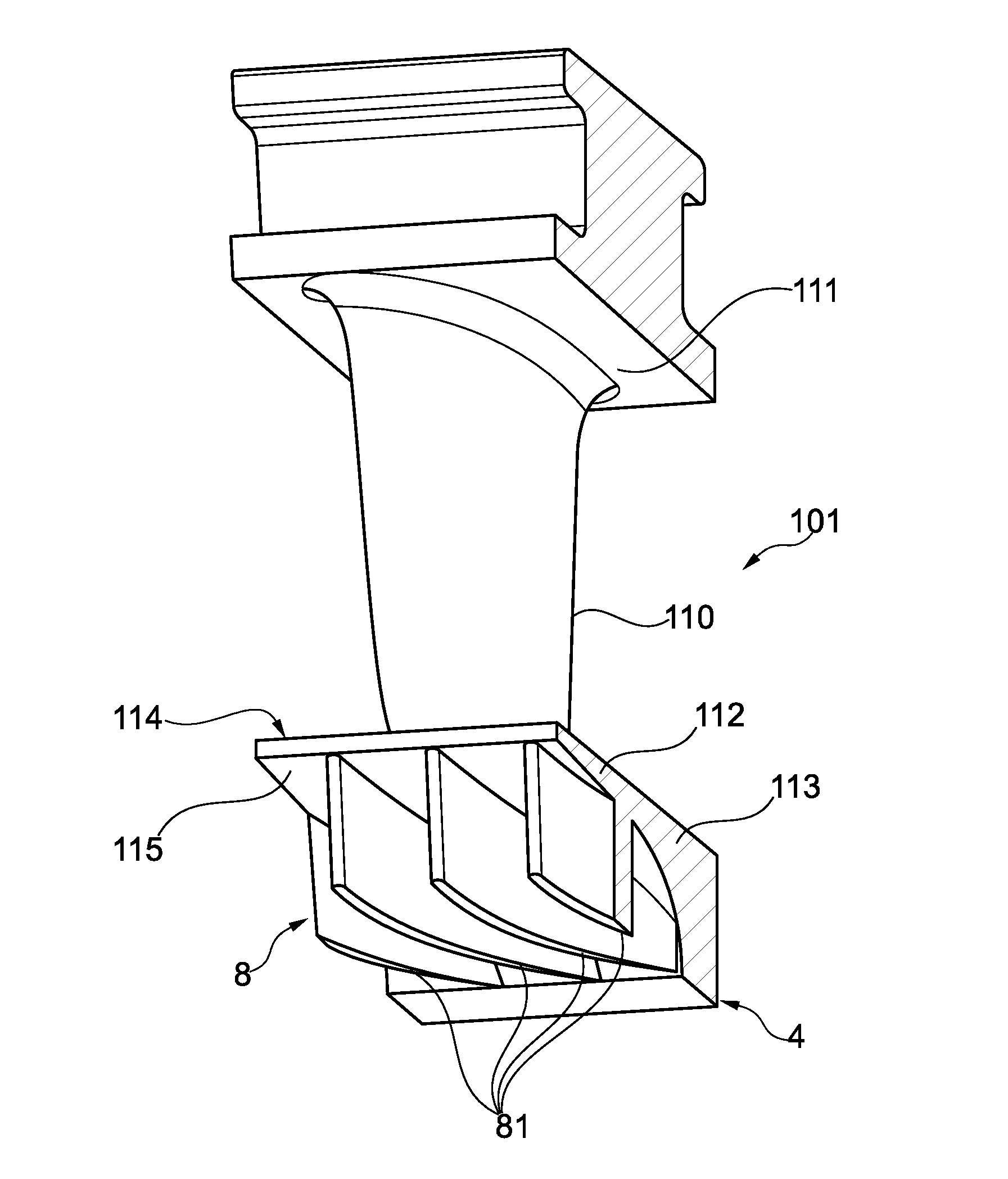
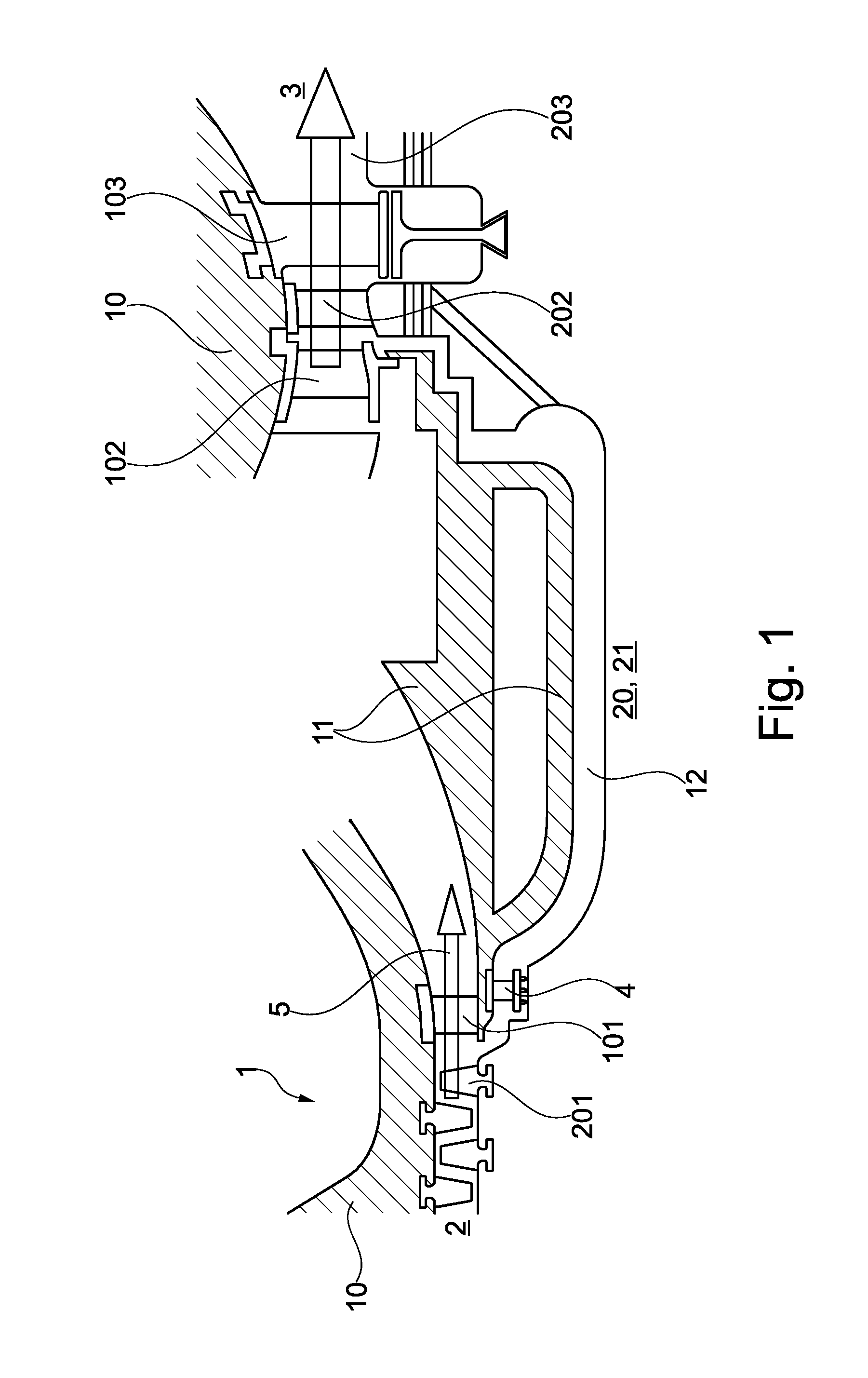
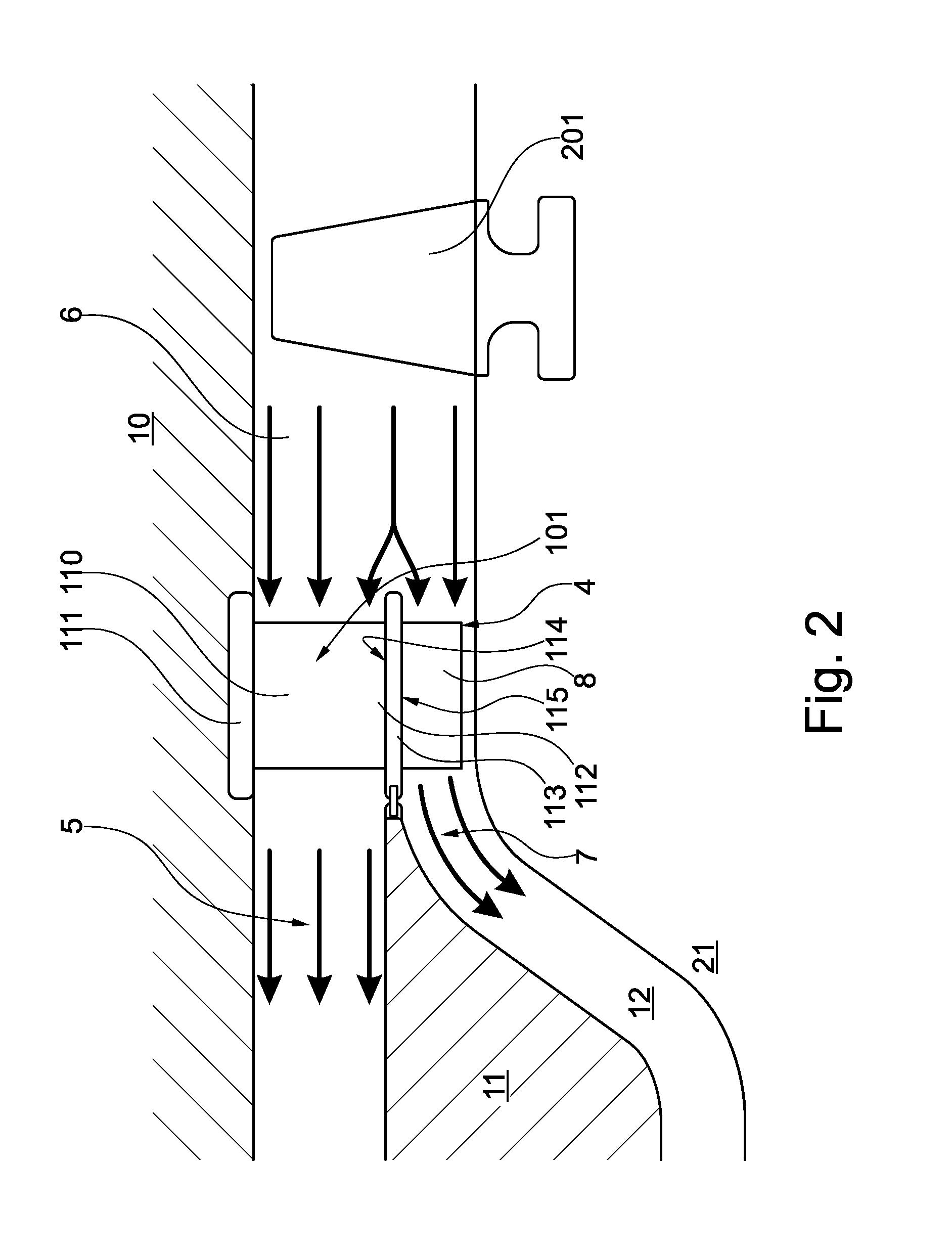
[0056]A first exemplary embodiment of a gas turbine engine applying the teaching of the present disclosure is shown in FIG. 1. The gas turbine engine 1 comprises a compressor 2 and an expansion turbine 3. It further comprises a stator 10 and the rotor 20. Only the last stages of compressor 2 and the first stages of the turbine 3 are shown in this figure. The last compressor stage comprises com...


PUM


Abstract

Disclosed is an engine, the engine having a compressor, an expansion machine, and a shaft, the shaft having a direction of rotation. The engine includes a compressed fluid main flow path, a flow divider arranged at and fluidly connected to the compressed fluid main flow path, and a duct fluidly connecting the flow divider and components of the expansion machine. The duct is arranged such that, when the engine is operated, a fluid is guided through the duct from the flow divider towards the expansion machine components. A flow deflector device is arranged within a flow path and configured to deflect and thereby accelerate a flow therethrough directed form the flow divider towards the expansion machine components in a tangential direction, wherein the deflection can be effected into the shaft direction of rotation.

Description

TECHNICAL FIELD OF INVENTION[0001]The present disclosure relates to the field of engines as described in the preamble of claim 1. In particular it may relate to working engines, and more particular gas turbines. It further relates to a guide vane element, in particular suitable for use in a turbo compressor of such an engine. It further relates to a method for cooling components of the engine.BACKGROUND OF INVENTION[0002]High efficiency engines generally require high working temperatures. Internal combustion engines may provide working fluids with temperatures far in excess of the temperatures endurable by most materials, especially when at the same time mechanical strength needs to be maintained. Components of engines serving for the expansion of hot compressed working fluids thus may require adequate cooling. This is in particular true for components exposed to a non-intermittent flow of high temperature fluids, in particular combustion gases, such as is the case for the component...

Claims


Application Information

Patent Timeline
Patent Type & Authority Applications(United States)
IPC IPC(8): F02C7/18F01D5/08F01D9/02F02C3/06
CPCF02C7/185F02C3/06F05D2260/201F01D9/02F05D2260/232F01D5/084F01D5/18F01D5/085F01D11/001F01D25/12F02C6/08F04D29/321F04D29/544F05D2260/14Y02T50/60
Inventor SIMON-DELGADO, CARLOSTAHENY, OLIVER JOSEPHOLMES, SVENBUSEKROS, ARMINALBERTI, LUCAJEMORA, DANIELROSSI, EUGENIOSIMONET, CHRISTOPHE
Owner ANSALDO ENERGIA SWITZERLAND AG
Why Eureka
Try Eureka