Tail cone of an aircraft

a tail cone and aircraft technology, applied in the field of tail cones of aircraft, can solve the problems of increasing the weight of the structure, and achieve the effects of improving the structural efficiency of the tail cone, reducing the weight of the structure, and simplifying the above mentioned structure of the tail con

Inactive Publication Date: 2016-06-30
AIRBUS OPERATIONS SL
View PDF11 Cites 9 Cited by
  • Summary
  • Abstract
  • Description
  • Claims
  • Application Information

AI Technical Summary

Benefits of technology

[0012]An aim of the invention is to simplify the above mentioned structure of the tail cone in order to make it easy to manufacture and assemble and to increase the structural efficiency of the tail cone.

Problems solved by technology

Manufacturing the previously mentioned structural elements and assembling them to the skin, including all the intersections between frames and beams is a difficult and time consuming task and in addition the intersections between longitudinal and transversal elements increase the weight of the structure because auxiliary joining parts have to be provided.

Method used


Image

  • Tail cone of an aircraft
  • Tail cone of an aircraft
  • Tail cone of an aircraft

Examples


Embodiment Construction

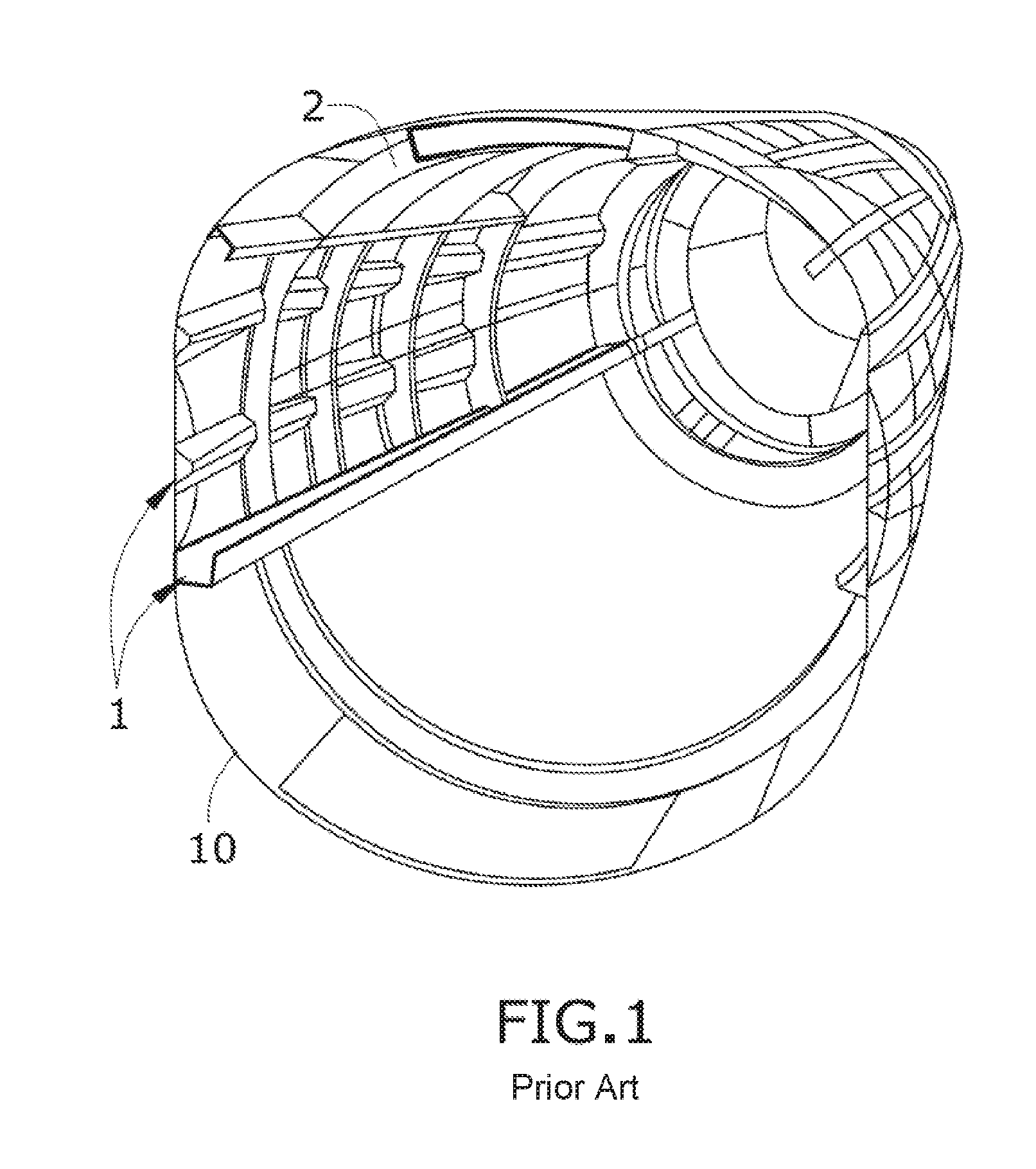
[0041]FIG. 1 shows a known tail cone comprising a skin (10), longitudinal structural members (1) located in the longitudinal direction of the tail cone and attached to the inner face of the skin (10), and transversal structural members (2) located in the transverse direction of the tail cone and also attached to the inner face of the skin (10).

[0042]The longitudinal structural members (1) shown in the figures are stringers (6) and beams (5) while the transversal structural members (2) mainly comprise frames (2). The stringers (6) could be omega or T shaped, and the beams (5) could have a C, J or H cross-section. The stringers (6) and beams (5) have intersections with the frames (2) as explained in the background of invention. The elements are made of carbon fiber reinforced polymer.

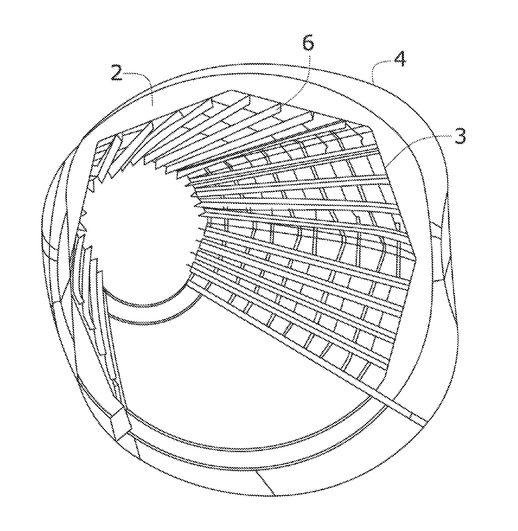
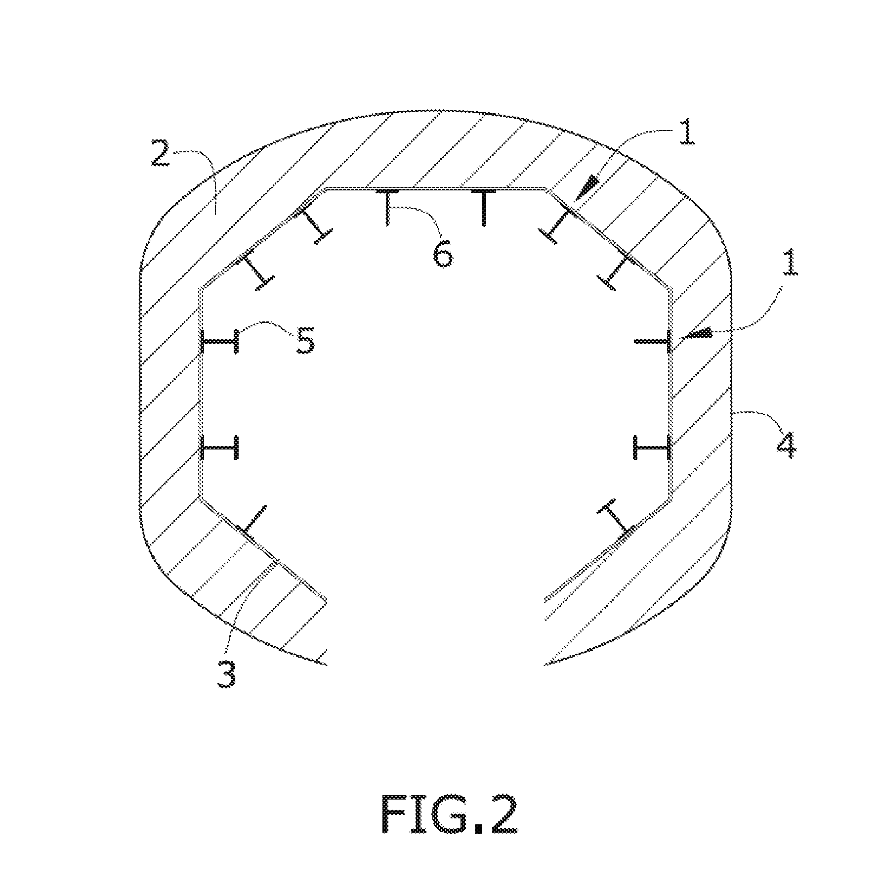
[0043]FIGS. 2 and 3 show an embodiment of a tail cone incorporating the present invention and made of composite material wherein the transversal structural members (2) are located between the external ski...


PUM

PropertyMeasurementUnit
skin thicknessaaaaaaaaaa
resistanceaaaaaaaaaa
weightaaaaaaaaaa

Abstract

A tail cone of an aircraft, more specifically a tail cone made of composite materials comprising an internal skin, an external skin surrounding the internal skin, longitudinal structural members located on the inner face of the internal skin in the longitudinal direction of the tail cone, and transversal structural members located between the external skin and the internal skin in the transverse direction of the tail cone.

Description

CROSS-REFERENCES TO RELATED APPLICATIONS[0001]This application claims the benefit of the European patent application No. 14382578.4 filed on Dec. 29, 2014, the entire disclosures of which are incorporated herein by way of reference.FIELD OF THE INVENTION[0002]The present invention refers to a tail cone of an aircraft. More specifically it refers to a tail cone made of composite materials.BACKGROUND OF THE INVENTION[0003]A known tail cone comprises longitudinal structural members, transversal structural members and a skin.[0004]The skin is internally reinforced with the longitudinal and transversal structural members such that the structural members are located on the inner face of the skin. Stringers, beams and frames can be mechanically attached to the skin or optionally stringers can be cocured to the skin while the other elements are riveted to the skin.[0005]The skin has to fulfill two different conditions, firstly to support structural loads mainly derived from the attachment o...

Claims


Application Information

Patent Timeline
Patent Type & Authority Applications(United States)
IPC IPC(8): B64C1/06B64F5/00B64C1/12
CPCB64C1/068B64F5/0009B64C1/12B64C1/06B64C1/061B64C2001/0072B64D2041/002Y02T50/40
Inventor AREVALO RODRIGUEZ, ELENA
Owner AIRBUS OPERATIONS SL
Why Eureka
Try Eureka