Combined Multipole Magnet and Dipole Scanning Magnet

a multi-pole magnet and beamscanning technology, applied in the field of ion implantation systems and methods, can solve the problems of complex structure, high-current implanters, and typically have a much shorter beamline, and achieve the effects of enhancing or reducing angle-dependent focusing, reducing beamline length, and saving beamline length

Active Publication Date: 2016-06-30
AXCELIS TECHNOLOGIES
View PDF8 Cites 5 Cited by
  • Summary
  • Abstract
  • Description
  • Claims
  • Application Information

AI Technical Summary

Benefits of technology

[0007]In both scanned beam and dithered pencil beam ion implanters, it is desirable to have as much control of various features as possible in order to adjust a shape of the ion beam, incident angles, and other desired characteristics of the ion beam. A scanner magnet is often a significant portion of a beam line of an ion implanter, but typically provides no overall static focusing. By combining a scanner with a multipole magnet (e.g., quadrupole or sextupole magnet), or a series of multipole magnets (e.g., in the case of a long scanner), a large savings in beamline length can be attained.
[0008]Scanner magnets can provide focusing depending on the angle of the scan. That is, the scanner magnets generally provide no focusing when the ion beam passes straight through, but provide stronger focusing when the ion beam is at or near a maximum bend angle. Thus, it can be advantageous to either enhance or reduce such angle-dependent focusing, whereby a multipole magnet is provided with a time-dependent waveform similar to that which drives the scanner magnet, in addition to any static DC component.
[0009]The scanner magnet is placed so that a waist of the ion beam (e.g., the narrowest portion in the x-direction) occurs at or near a vertex of the scan. The waist of the beam is also a preferred place for the multipole magnet of the present disclosure, as it is possible to add focusing in the perpendicular direction to the waist (e.g., in the y-direction) without greatly affecting the beam in the waist direction. In addition, should a corrector be used after the scanner, the corrector will parallelize out any defocusing in the waist direction. The present disclosure thus advantageously provides a combined multipole magnet with a dipole scanning magnet.
[0010]The combined magnet, for example, is made of steel laminations to reduce eddy-current loss in the steel yoke. The scanner coils can be of any shape and be designed based on various design criteria. For example, simple coils illustrated in the figures can be wrapped around the yoke, or bedstead coils or other coils can be implemented. The coils, for example, are in vacuum or in air. The multipole coils, for example, can also be similar coils, with the addition of flux compensation. One of the figures shows a Panofsky-type quadrupole nested inside dipole coils.

Problems solved by technology

High-current implanters, however, typically have a much shorter beamline due, at least in part, to the low energies associated with the ion beam, wherein the high-current ion beams tend to lose coherence with longer beamlines.
Such a scanning of the workpiece often requires a complex architecture for uniformly translating the workpiece through the stationary ion beam.
However, such a scanner magnet often inhabits a significant portion of real estate along the beamline.
However, since the scanner magnet consumes a great deal of beamline length, the implementation of such focusing magnets or optics is conventionally limited.

Method used


Image

  • Combined Multipole Magnet and Dipole Scanning Magnet
  • Combined Multipole Magnet and Dipole Scanning Magnet
  • Combined Multipole Magnet and Dipole Scanning Magnet

Examples


Embodiment Construction

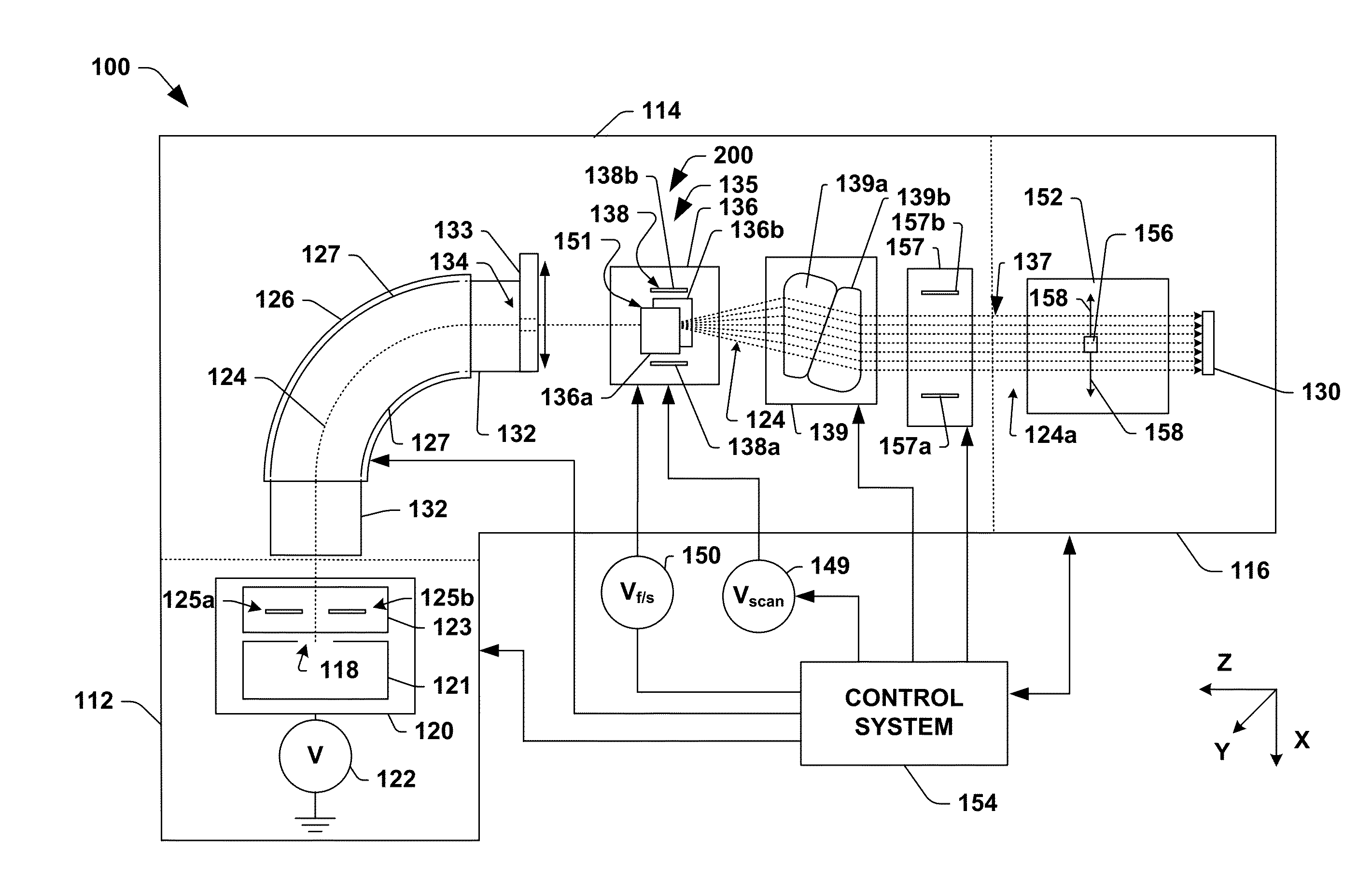
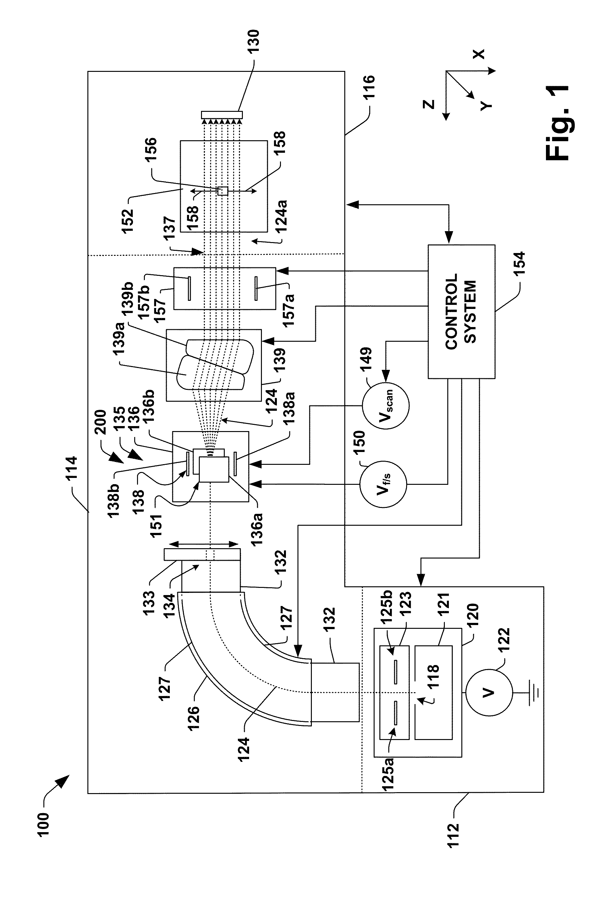
[0024]The present disclosure is directed generally toward an ion implantation system and method for implanting ions in a workpiece, wherein a beam of ions is generally concurrently magnetically scanned and focused via a combined multipole and dipole scanning and focusing magnet. Accordingly, the present disclosure will now be described with reference to the drawings, wherein like reference numerals may be used to refer to like elements throughout. It should be understood that the description of these aspects are merely illustrative and that they should not be interpreted in a limiting sense. In the following description, for purposes of explanation, numerous specific details are set forth in order to provide a thorough understanding of the present disclosure. It will be evident to one skilled in the art, however, that the present disclosure may be practiced without these specific details.

[0025]Referring now to the Figures, FIG. 1 illustrates ion implantation system 100 in accordance...


PUM


Abstract

A combined scanning and focusing magnet for an ion implantation system is provided. The combined scanning and focusing magnet has a yoke having a high magnetic permeability. The yoke defines a hole configured to pass an ion beam therethrough. One or more scanner coils operably are coupled to the yoke and configured to generate a time-varying predominantly dipole magnetic field when electrically coupled to a power supply. One or more focusing coils are operably coupled to the yoke and configured to generate a predominantly multipole magnetic field, wherein the predominantly multipole magnetic field is one of static or time-varying.

Description

REFERENCE TO RELATED APPLICATION[0001]This application claims priority to and the benefit of U.S. Provisional Application Ser. No. 62 / 096,968 which was filed Dec. 26, 2014, entitled “COMBINED MULTIPOLE MAGNET AND DIPOLE SCANNING MAGNET”, the entirety of which is hereby incorporated by reference as if fully set forth herein.FIELD OF THE INVENTION[0002]The present invention relates generally to ion implantation systems and methods, and more specifically to a combined multi-polar focusing magnet and beam-scanning magnet for controlling an ion beam.BACKGROUND OF THE INVENTION[0003]Conventionally, ion implanters are utilized to place a specified quantity of dopants or impurities within workpieces or semiconductor wafers. In a typical ion implantation system, a dopant material is ionized and accelerated, therein generating a beam of ions. The ion beam is directed at a surface of the semiconductor wafer to implant ions into the wafer, wherein the ions penetrate the surface of the wafer and...

Claims


Application Information

Patent Timeline
Patent Type & Authority Applications(United States)
IPC IPC(8): H01J37/141H01J37/317H01J37/08
CPCH01J37/141H01J2237/1415H01J37/3171H01J37/08H01J37/1475H01J2237/152H01J2237/04922H01J37/05H01J37/1472
Inventor EISNER, EDWARD C.
Owner AXCELIS TECHNOLOGIES
Why Eureka
Try Eureka